How Smoke Detectors Actually Work
2021
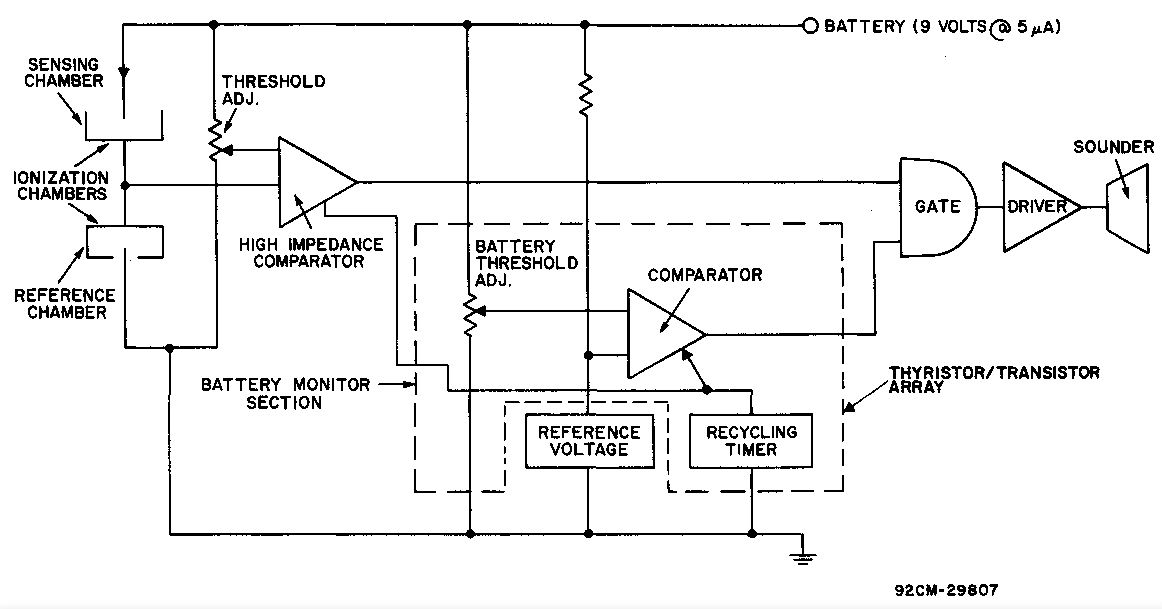
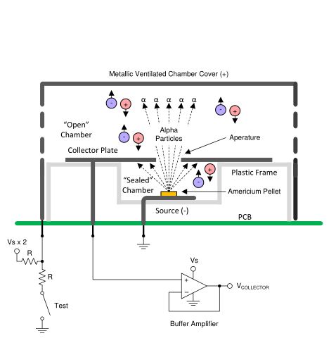
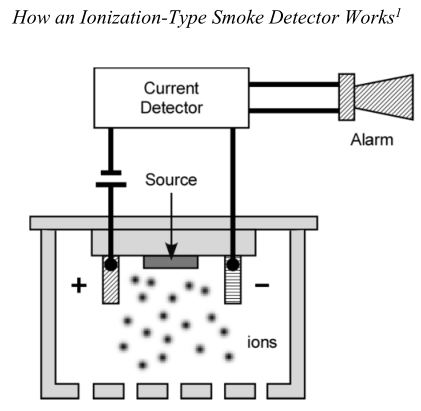
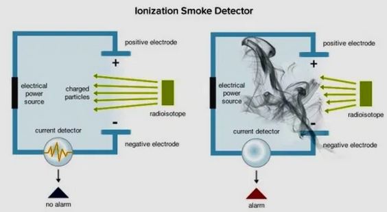
Anyone who has bothered to ask knows that typical residential smoke detectors contain an Americium-241 source that ionizes air and allows a small current to flow. That current is interrupted by smoke because the ions carrying the current attach to the smoke molecules. If you research a bit more, you will find that there are, in fact, two ionization chambers. One that is open to the air and one that is 'sealed' (really its just a pocket that is open to the open chamber at one end). What you cannot easily find, though, is how the circuit is actually implemented. The vast majority of circuit diagrams for smoke detectors online are oversimplified to the point of being simply wrong. They show current being measured between two electrodes. This obviously doesn't jive with the fact that there are two effective chambers.
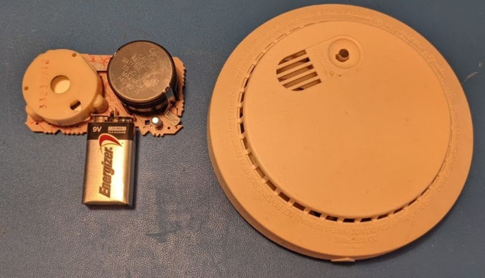
Typical Smoke Detector
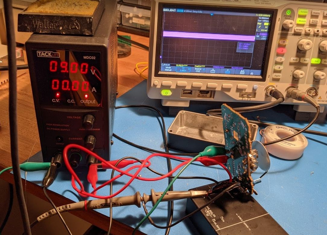
I saw a posting for two free "fire alarms" on Craigslist one morning, so I biked over to pick them up in order to find out how they actually work. It actually turns out that smoke detectors don't directly measure current at all -- they respond to changes in voltage on a detector plate that separates the open and 'sealed' chamber. The detector plate is effectively floating since it is tied to a high input impedance comparator and buffer amplifier. In normal operation, the currents in the two chambers are balanced and the detector sits at about half the supply voltage. If current in the open chamber is reduced due to smoke, the voltage on the detector plate will rise and, once it exceeds a certain threshold, will cause the comparator to trigger the alarm circuit. I also measured the maximum ion current to be only 10pA which is significantly less than the typically stated value of 100pA.
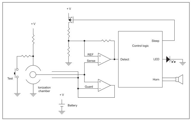
Actual Circuit
Removing the cover from the ionization chamber caused the smoke detector to alarm, so I desoldered the piezo-electric buzzer to preserve my hearing and sanity. The 'open' chamber is the large volume between the top plate and detector plate. The 'sealed' chamber is the small volume between the source and the detector plate. Obviously smoke can get into the sealed chamber as well, but it is more out of the way and the stronger electric field in this region (closer electrode spacing) probably reduces the effect of smoke attaching to ions before they can be collected.
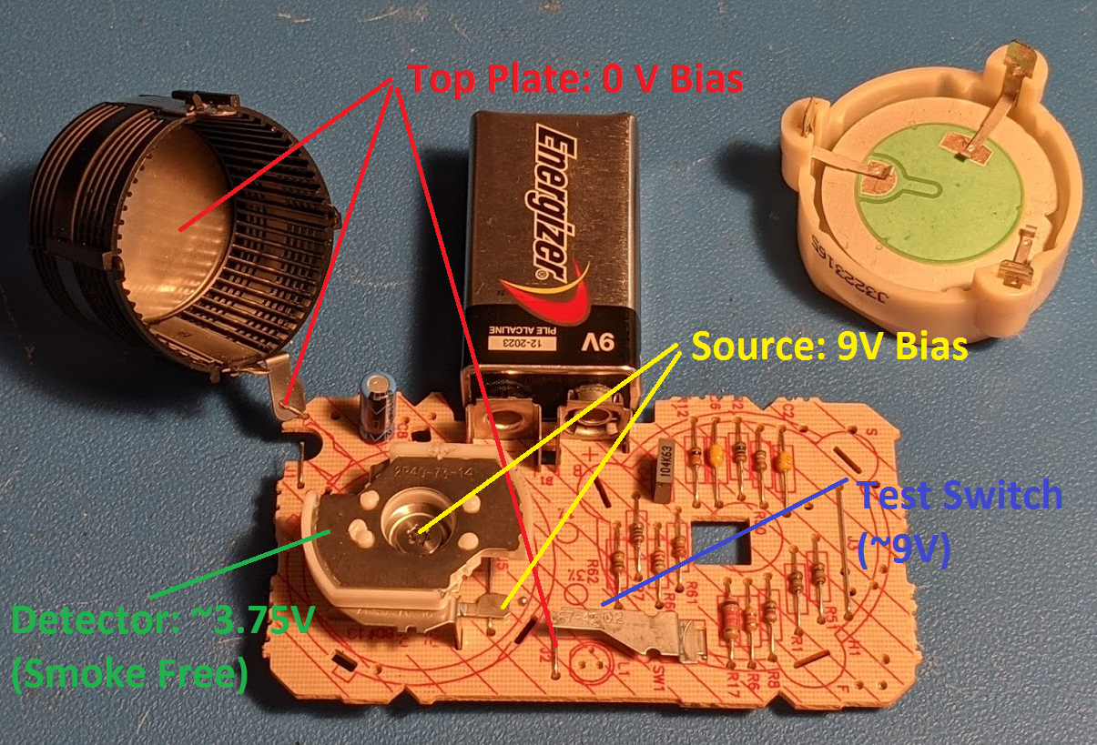
Bias Voltages of a Smoke Detector Ionization Chamber
With the source at 9V and the top plate at 0V, the detector plate rises to an intermediate voltage around 4.5V in my smoke detector. When smoke enters the open chamber, the current flow in that chamber is reduced and the voltage of the detector plate rises. The test switch applies 9V to the top plate of the open chamber which results in the detector plate voltage rising just as it would when smoke is in the chamber, so the test button on a smoke detector excercises the whole circuit in a pretty realistic way.
Low Leakage Construction Techniques
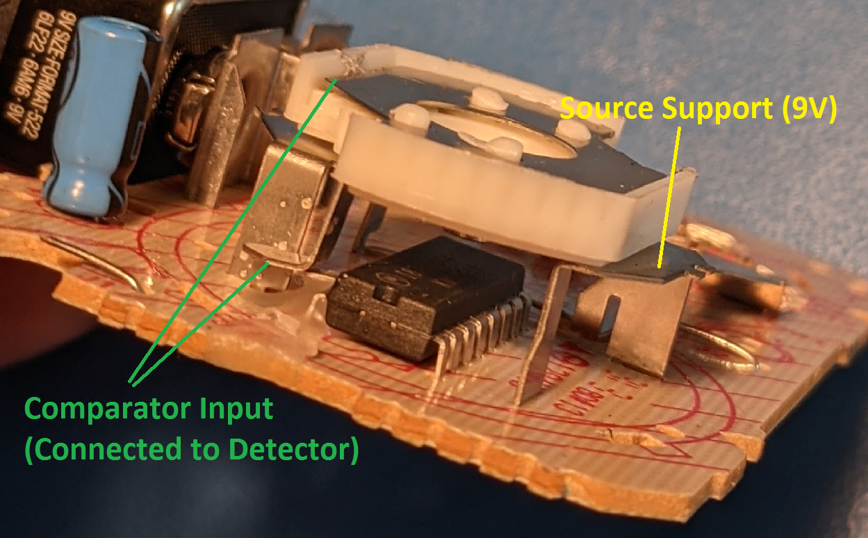
You can't use a multimeter to measure the voltage of the detector plate. The impedance is too high, and the multimeter will read zero volts. To measure this voltage, I modified my picoammeter circuit to instead be a buffer amplifier. The extremely low leakage of the LMP2231 allows the voltage to be measured without loading the circuit appreciably. The need to maintain low leakage is apparent in the smoke detector circuit design: the comparator input pin is lifted and surrounded by a waxy substance to reduce leakage through the circuit board and from surface contaminants on the circuit board.
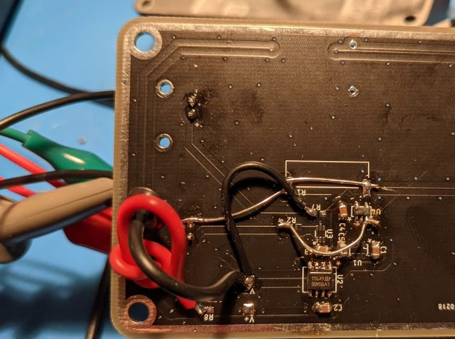
Hacked Together Low Leakage Unity Gain Buffer
I connected the output of the OP-AMP to the case to act as a guard for the measurement, but that added enough of a capacitive load that the OP-AMP oscillated (output to input may have also been responsible for the oscillation). That just added high frequency noise, though, and the voltage of the detector was still easy to observe.
I discovered after this test that the pins adjacent to the input are a driven guard ring. Inside the part, the input is connected to both a comparator and a unity gain buffer that drives the adjacent pins of the input to the same voltage to reduce leakage. I could have just probed those pins instead of hacking together a buffer of my own, and I likely would have gotten a much cleaner signal.
Detector Voltage Measurement Setup
Just a wisp of smoke from a blown out match was all that was required to get a full volt change on the detector plate. The threshold voltage of the comparator in my smoke detector was about 5.15V (with some hysteresis) which I found by driving the detector plate with an external power supply and seeing at what voltage the unit alarmed. The circuit is not even a window comparator (you can short the detector plate to ground and it will not alarm) -- it just checks that it is below 5.15V.
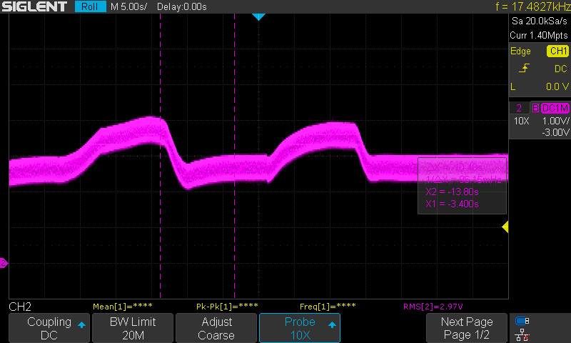
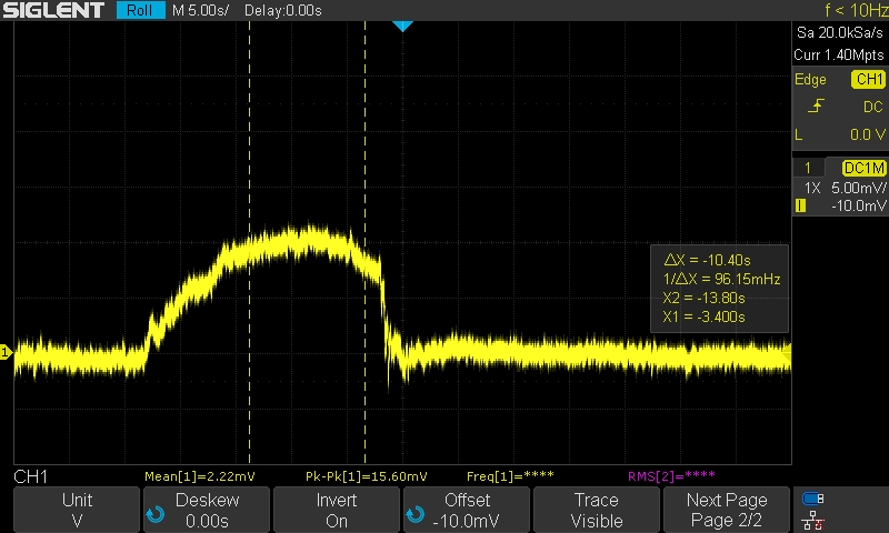
Detector Voltage in Response to Smoke
The above plot shows the detector plate voltage (plus the output oscillation noise of the buffer amplifier) after smoke is introduced to the chamber, blown out of the chamber, introduced to the chamber a second time, and then blown out again. The nominal smoke-free voltage shown here is a bit lower than the normal 4.5V because I used a lower bias voltage across the chamber so that I would stay in the common mode voltage range of my buffer.
Current Measurement
My picoammeter / ionization chamber has an auxiliary input, so I wired it up to the smoke detector ionization chamber to see what the current actually is. Since my box uses a 2.5V common mode voltage, I had to drive the top plate to a negative voltage to get the same current balance as in the original circuit. The biases in my setup are 6.5V from the source to the detector plate and 6.5V from the detector plate to the top plate, so 2V higher each than the original circuit, but still balanced.
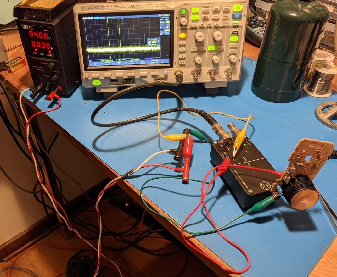
Test Setup
The current of the 'closed' chamber can be measured by setting the bias voltage of the top plate to the common mode input voltage of the OP-AMP (you can't just remove the top plate because it electrostatically shields the OP-AMP input from mains noise and that noise will swamp the measurement). That current is right around 10pA.
'Sealed' Chamber Current: 10pA. Picoammeter Gain 1V/nA
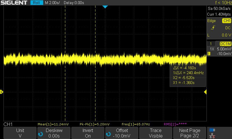
Therefore, the current you would expect to measure if smoke completely stopped the flow of current in the top chamber and did not affect the flow of current in the bottom chamber would be 10pA. That is, in fact, what I saw when I let the top chamber fill with smoke from a smoldering paper towel:
Measured Current Change From Smoke: 10pA. Picoammeter Gain 1V/nA
The abrupt falling edge is from fanning the smoke out of the chamber as you would do with your hat after your kitchen smoke detector went off while cooking.
The detector plate voltage was held constant in this test. In normal operation, the voltage will rise or fall until a new equilibrium voltage is reached. Note that, with a 1Gohm feedback ammeter, I only saw a 10mV signal. The voltage of the detector plate rose by around 100x this when alowed to float, so circuits that look at the voltage of the detector plate rather than the current into it have much higher sensitivity.
Correct Circuits Online
The only correct circuit I could find in a Google Images search was from a 1977 IEEE paper called "Bipolar-MOS and Bipolar IC's Building Blocks for Smoke-Detector Circuits". I haven't even read the paper because it is behind a paywall, but this image showed up on Semantic Scolar:
Correct Smoke Detector Circuit from "Bipolar-MOS and Bipolar IC's Building Blocks for Smoke-Detector Circuits"
This shows the two chambers biased opposite how they were in my smoke detector, but the principle is the same: the detector alarms if the voltage, which is set by the balance of currents, of the detector plate passes a certain threshold. Its far cheaper to use a high input impedance comparator then it is to actually bother measuring the current, so it is no surprise that that is the approach taken in mass market smoke detectors.
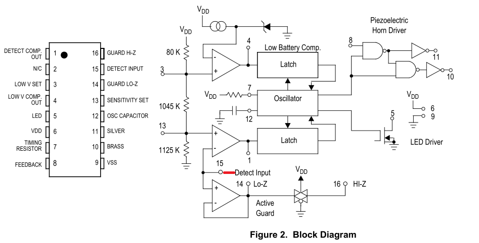
Typical modern ionization smoke detector ICs have an extra part not included in the circuit from 1977: a unity gain buffer to drive a gaurd ring. A better source of truth in smoke detector design than Goodle Images is a datasheet for a smoke detector IC. Here are several:
Typical Ionization Smoke Detector Circuit from MC145017 Datasheet
Typical Ionization Smoke Detector Circuit from Allegro A5348 Datasheet
Typical Ionization Smoke Detector Circuit from Circuit Celler Magazine

Accurate Ionization Chamber Diagram from Circuit Celler Magazine
I found the above article after writing this page. Its a reasonable overview of ionization smoke detectors, but the calculation of ionization current in it is obviously wrong (it predicts 2nA of current). The equation shown in the next section.
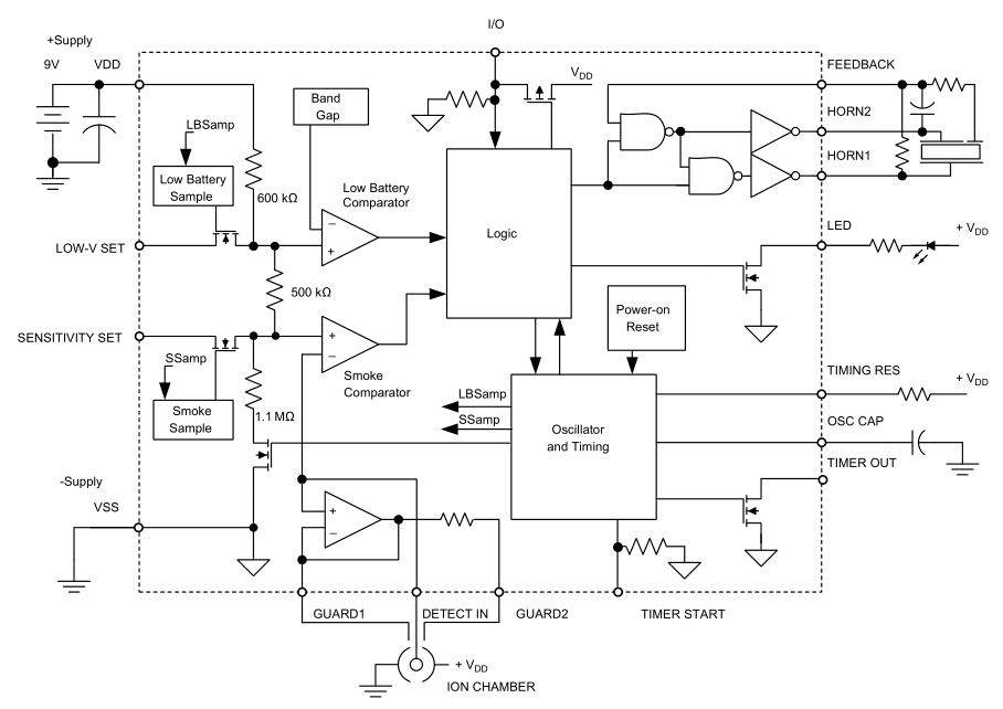
Functional and Accurate Ionization Smoke Detector Diagram from Texas Instruments App Note SNOA960
This is the only diagram that shows that there are two chambers and that the 'closed' chamber isn't really closed. The app note also provides some insight into variation in typical commercial ionization chambers: "Depending on the ratio of the chamber volumes, clean air output voltage on collector plate is between 1/2 to 5/8 the chamber voltage."
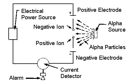
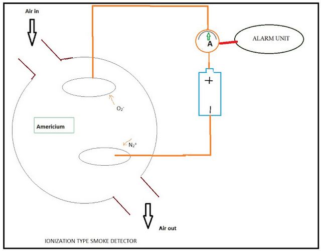
Incorrect Circuits Online
For the layman, all of the below circuits are sufficient for understanding the basics of how a smoke detector works, but they are misleading if you are the kind of person who wants to build one from scratch. I know there is a place for simplification in order to aid understanding, but it is frustrating that the truth is hidden behind thousands of these misleading examples.

Incorrect Circuit from the NRC

Incorrect Circuit From College Physics, 3 rd Ed. Serway & Faughn, p. 1025
All of the previous examples are wrong because they show the current through a single chamber being measured. This last example is from the embedded video on the Wikipedia page for smoke detectors. Let's pretend that the values shown in the circuit are actually correct and ignore the fact that the ionization chamber is shown wired in parallel with a voltage source. 100pA into a 45 Mohm resistor will, per Ohm's law, produce only 4.5mV. The device shown is a P-channel MOSFET. If the source to gate voltage of this MOSFET is above its threshold voltage, it will be on. The source to gate voltage when smoke is not present will be 4.4955V, and when smoke is present it will be 4.5V. In other words, assuming a typical threshold voltage of a few volts, the MOSFET will always pass current to the horn and the alarm will always be going off.

This circuit could conceivably work if the 45Mohm resistor were removed, a low Vgs threshold MOSFET were used, and the detector were wired up with a positive bias on the open chamber top plate. In that case, smoke would interrupt current flow into the detector and its voltage would fall from 4.5V down to a voltage low enough to allow the MOSFET to conduct. There may at one time have been smoke detectors that used a circuit like this, but I'm pretty sure that comparator based circuits have been in use since the '70s since they allow for much tighter control of the alarm threshold voltage.
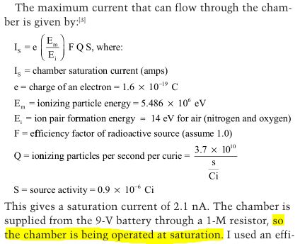
Incorrect Ionization Current Equation from Circuit Celler Magazine
The above equation does tell you the saturation current from air fully ionized by a 1uCi AM-241 source, but the problem is that ionization chambers in smoke detectiors are not operated in the saturation region. The saturation region is where electric field is strong enough to collect all of the electrons and ions before they recombine. Stated another way, a chamber is in saturation region if an increase in voltage does not increase the measured current. Even in a smoke-free environment, most of the electron-ion pairs are lost due to recombination because the electric field is far below the level required for saturation, so the fact that this equation predicts 2nA of current while I only measured 10pA is not a surprise.