Lithium Ion Cell Holders
2014-2016
When you build a battery that contains hundreds of individual cells, connecting them all together in a manageable way becomes a problem. I finally settled on this method using 3D printed cell holders and nickel tabbing wire after half a year of brainstorming and testing back in 2014/2015. This was the first attempt by the Missouri S&T Solar Car Team to use cylindrical cells. Prior to this, the team used Dow Kokam Pouch Cells in a pretty terrifyingly unsafe pack.
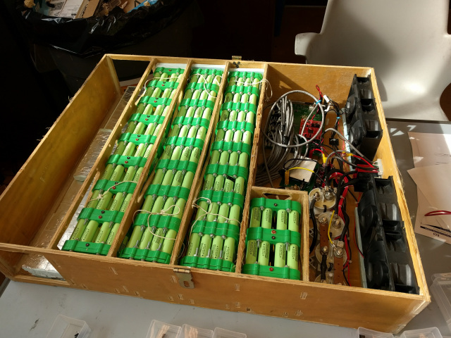
2016 Battery Box Testing with both 2015 and 2016 Modules
Construction:
The cells are held in place by friction. When a module is assembled, the two holders are carefully press fitted together with the cells in between. Holders can be removed, but the outer wrappers of the cells is normally damaged in the process. The modules are surprisingly sturdy for just being press fitted. A full bank of eight modules connected end to end does not sag at all if it is held by one end parallel to the ground. The first version of these holders included a hole in the very center of the pack so that a threaded nylon rod could be inserted to hold everything together, but it did not end up being necessary. The first version also had six screws per module which was definitely more than necessary.
For the first version of these cell holders, different sized holes were printed until the ideal size setting could be found. You do not get exactly what you specify in CAD out of a 3D print, so the value that had to be set was different for every printer. For the second version, the holes were printed slightly undersized and then reamed out with a custom tool machined from aluminum. This let us get much closer tolerances and enabled us to use the same files on multiple printers.
For temperature sensors, we used one wire serial TO-92 packaged devices soldered to the end of a wire and covered in some heat shrink. The first step in the assembly process is to place the four center cells and then use thermally conductive epoxy to secure the temperature to the cells. The wire stub is left long so that it can be crimped at the correct length into the balance connectors later. Only one side per module has a temperature sensor.
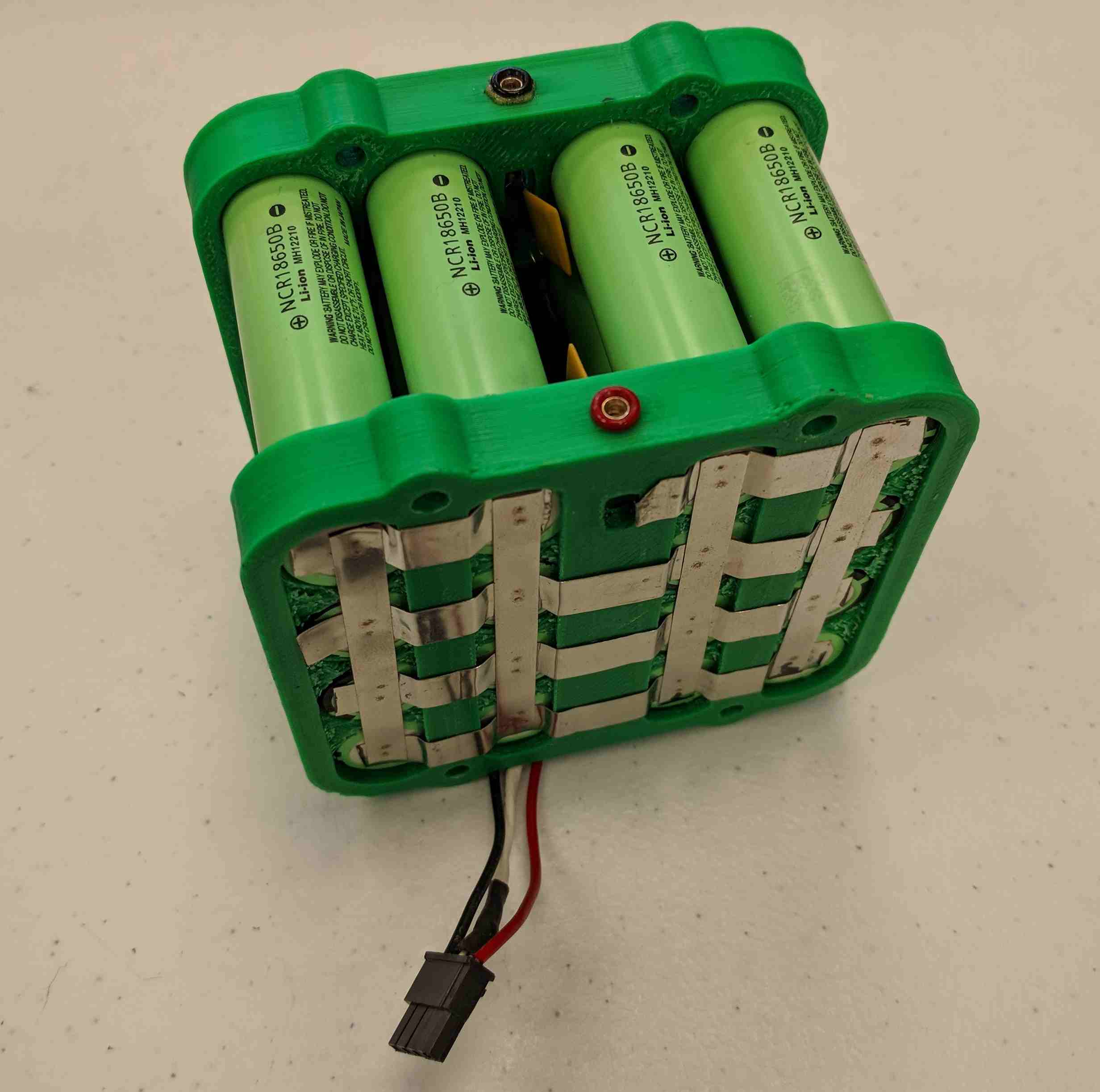
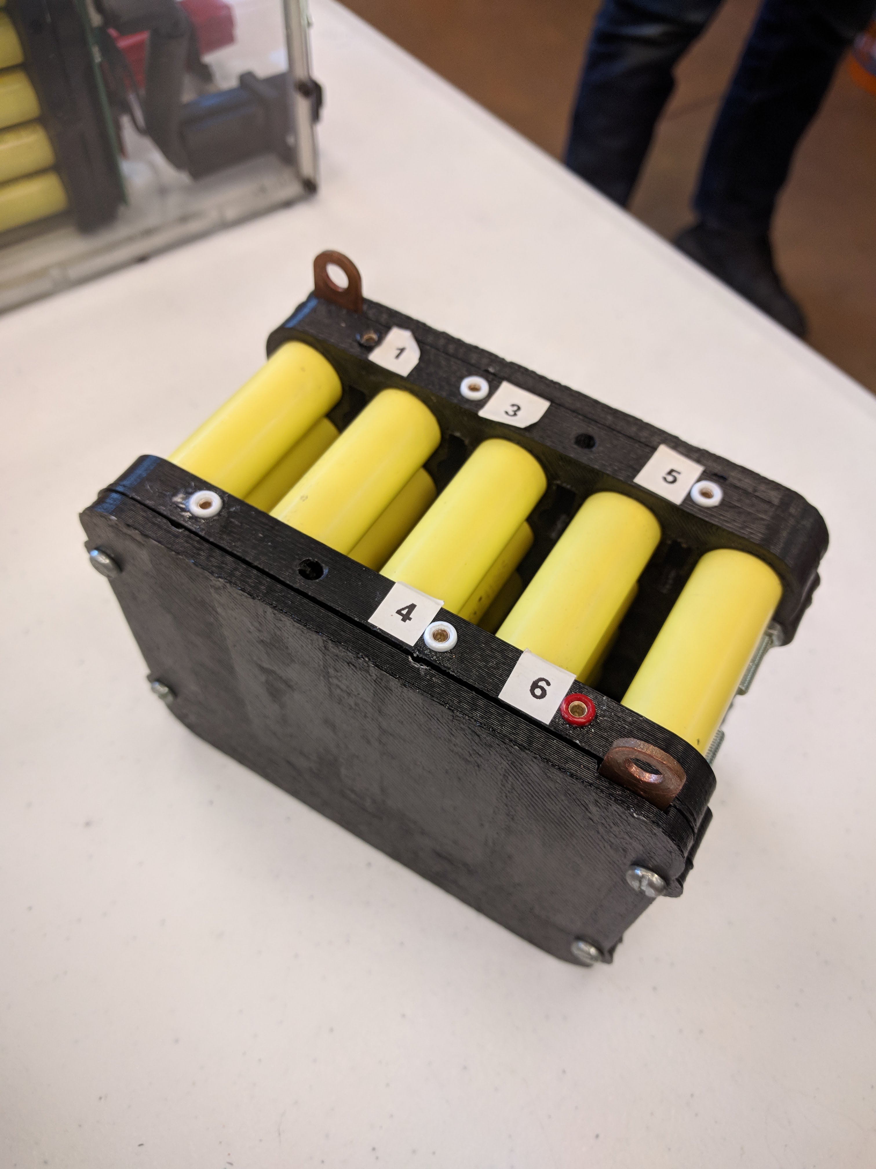
2016 Battery Module
Once the rest of the cells are press fitted into a module, the cells are welded together using nickel tabbing strip. The strip is first welded left to right for each row in the above image. The three flats running top to bottom on the holder provide places to concentrate the force holding the tabbing strip of one pack to the tabbing strip of another pack. Once the rows were tabbed, thinner tabbing wire was run along the four top to bottom channels to keep the module balanced. Tabbing wire was placed in all four channels because even though the balancing current is quite small it is good to be able to spread the current to a different part of the face of the module in the event that there is a poor electrical connection to the next module at one part of the face.
In practice, the contact resistance between the modules was extremely low. With the four screws properly torqued, the contact resistance was in the neighborhood of 100 micro-ohms. Extensive tests were done to show that even under worst case conditions (no screws installed — modules barely touching each other) the resistance did not become high enough to pose a localized heating risk at normal operating currents.
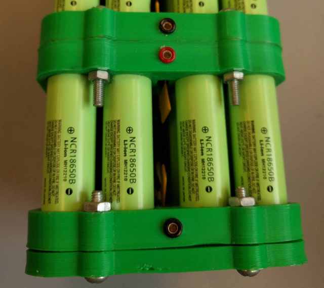
Tip Jacks on 2016 Jack
The hole at the top of the cell holder and the associated window on the outer face allow tip jacks to be fitted into the modules. The tip jacks allow the voltages of individual modules to be quickly checked with a multi meter, and they allow high current balance connections to be connected into a bank for initial charging with a charger such as an iCharger 208B. The tip jacks are connected to the cells by soldering a short piece of tabbing wire to the bottom of the jack and then spot welding that stub to the rest of the tabbing wire.
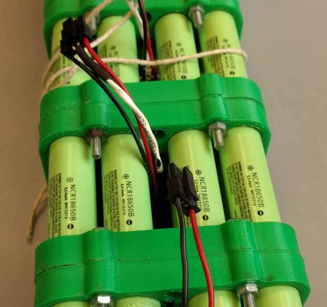
Balance Connectors on 2015 Pack
The last step in the assembly process is to add the voltage sensing / balance connector. The battery management system (BMS) needs to know the voltage and temperature of every module at all times to ensure that the system isn’t driven beyond what it is rated for. To protect against an accidental non-current limited short circuit from happening somewhere in the balance lines, 1A polyswitches are connected in series with both the positive and negative balance line. These are the two yellow squares that can be seen on the inside of the pack in the above image. They are soldered on one side to their corresponding tip jack and the other side wens through a short wire to the module’s balance connector.
Prototype Balance Connection Board
It was still time consuming to connect and disconnect all of the balance connections when doing maintenance on the banks, so I designed (my longest to date) PCB to consolidate all of balance lines for a bank into one connector. The individual modules would plug into their respective slots on this board and then a single blind mate connector at the end of the bank would carry all the relevant lines back to the BMS. The pack design changed to 12 cell modules after I graduated, so the team never got a chance to try out this board. The board was designed so that it could be cut for the required number of modules.
The board was made by EasyEDA for ridiculously cheap. EasyEDA is based in China, but their quality is quite high and their turn around times are quite fast for them being on the other side of the world. They sponsored the team after Sierra Circuits dropped all of their student team sponsorships. Sierra has reasonable quality as well and is my go-to when I need to get a prototype board manufactured in the United States.
What Others Are Using
Many solar car teams are rather secretive. Here’s what I’ve managed to find on other teams using 18650 cells. S&T has some shots of their pack online as well.
Stanford
Stanford Solar Car Module
https://www.mercurynews.com/2011/08/09/stanford-solar-car-on-display-before-big-race/
The Standord Solar Car team uses similar cell holders. The differences are that they use a sheet of, presumably, nickel instead of multiple individual strips. I looked into doing this, but the cost of buying and forming nickel sheet was much higher than just using individual strips. The continuous sheet does have a nice look to it, though. Distributed BMS boards also help cut down on wire clutter. Presumably the boards on each module pass data in series so that each bank only has one data connection back to the central BMS.
Stanford Solar Car Pack
Stanford also close packs their cells whereas ours have ample spacing between cells. Space isn’t normally a limiting factor in a solar car. There is a lot of room inside the body to place the cells, and it can get very hot when racing during the summer. Extra room between the cells means that air can get in to the inner cells and carry away heat that would otherwise be trapped. During the summer race in Austin, TX in 2015, our pack was operating right at the edge of the thermal trip point where we would have to disable charging, so being able to cool these packs is important.
Berkley
Berkley Solar Car Pack
Berkley Calsol takes a somewhat minimalist approach. The cells are spot welded together with tabbing wire and each ‘module’ sits at a distance from the others. I would imagine that this method adds a good bit of lead resistance from the thin tabbing wire, but the batteries have good air circulation. A pack like this will tolerate individual cell failure better because single cells can be replaced and because the damage caused by a cell catastrophically failing will be more limited than in a pack where the cells are connected end to end. 18650 cells vent out their positive ends, so the adjacent module will probably be sprayed by electrolyte during a failure. That said, the only time I have ever seen an 18650 vent was after intentional and sustained extreme overcharge.
S&T Robotics Team
Unlike Solar Car teams, the robotics team only needed a battery that would last for around 20 minutes at 500W or so. For this application, a single module with both series and parallel connections makes sense. I modified my Solar car battery holder design for this application and helped the team assemble the module.
Missouri S&T Robotics Team Battery
The tip jacks on top serve as the balance connections back to their BMS, and two copper bus bars bring the negative and positive battery connections out the top of the pack. The bus bars were connected by first soldering nickel tabbing wire to copper bars and then spot welding the nickel strips to the batteries. It required careful alignment during soldering to ensure that the tabbing wire lined up with the cells, but it saved the batteries from being exposed to the heat of soldering the strips to the bus bar. 3D printed covers blocked access to the exposed terminals and made for a tidy little pack. The cells are LG HE4. In this application, high power density is more important than high energy density.
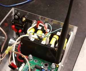
Battery with BMS and Relay
Sierra Circuits wrote a nice article about their electrical systems. While their electrical system was a bit rough, they built something that worked.
Hobbyists
There are some terrifying lithium ion batteries online. People mix and match cells salvaged from laptop batteries. People operate without battery management systems. People solder directly to cells. All of this is stuff that you can do and often get away with, but I would never allow such a battery in my house or garage. The risk of it failing and causing extensive property damage just isn’t worth it.
I would recommend that no one build a battery pack like the one in the video. Soldering directly to lithium batteries is not a good idea. The materials used inside the cell can not hold up to the temperature. The correct way to assemble cell modules is to use a captive discharge spot welder. The ‘fuse’ wire could have been welded to the cells just as easily as nickel strip.
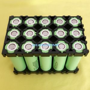
Chinese Battery Brackets
There is nothing inherently wrong with the stackable injection molded battery brackets that you can buy cheaply from China. I considered using them, but there isn’t a good way of clamping them together. We wanted individual replaceable modules and not large monolithic tabbed together battery banks, so this wasn’t the right solution for our application. There brackets may work well for something like an electric scooter or robotics project, though.