Common Slot Breakout
2020
In 2020, there was a glut of high power hot swappable HP server power supplies on eBay for some reason. I think a lot of servers using this form factor were being taken offline around this time and that the secondary market had not yet caught up to the capabilities of these supplies. Three friends and I all purchased 12V 100A AC to DC supplies for around $20 each. The interface si pretty simple: short two pins together and the supply turns on. Rather than solder wires to the card edge connector of these supplies, I made a custom breakout board.
Now in 2021, these supplies (at least the model I have: DPS-1200FB) sell for $50, and eBay is littered with breakout boards to power GPUs for Bitcoin mining. There isn't anything special about by breakout board; I just wanted to provide connectors useful for a hobbyist lab bench.

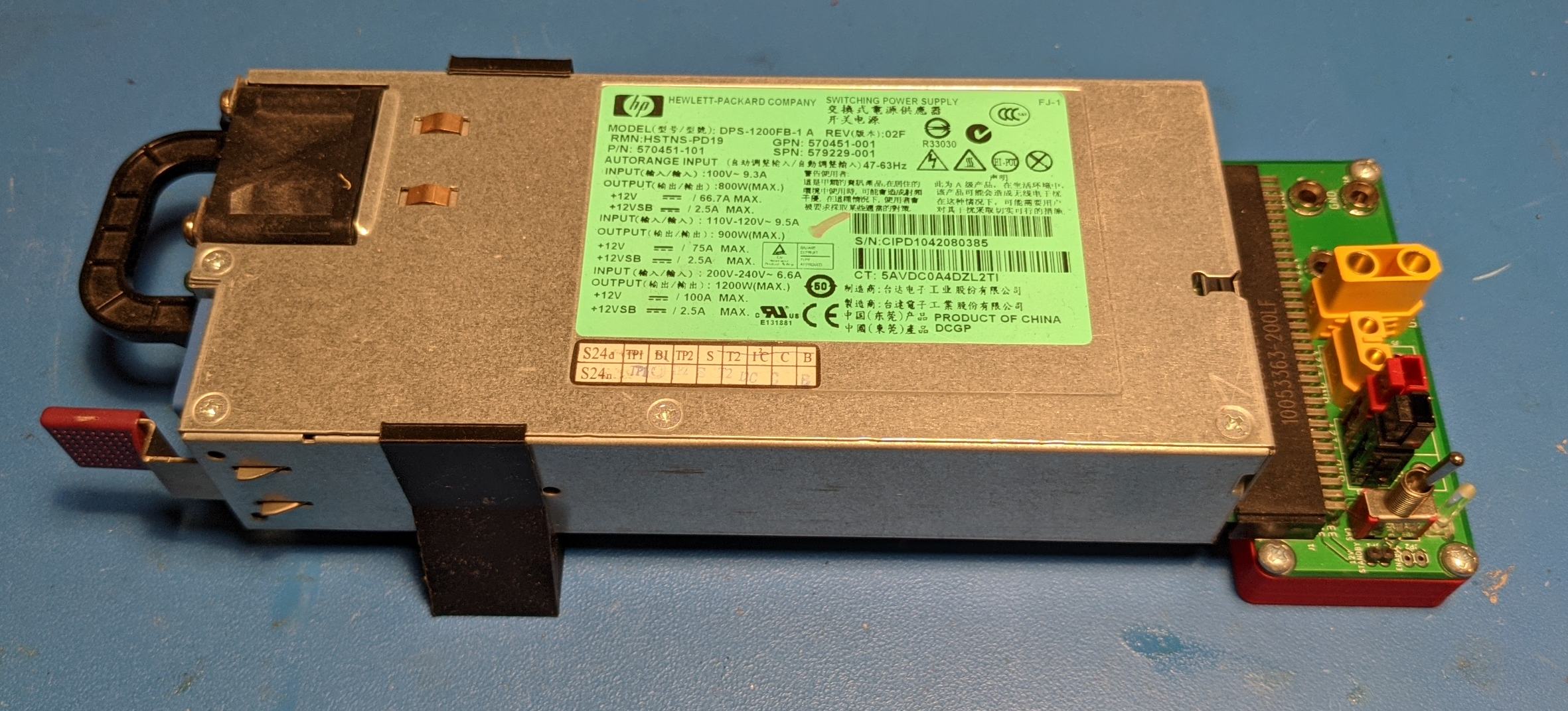
12V 100A Surplus Server Supply With 3D Printed Support and Breakout Board
SchematicLayout
EagleCAD Files
3D Print Files
Overview
I normally use banana plugs and Anderson Power Poles, but XT-60 and XT-90 connectors are commonly used in other RC / hobby stuff, so I threw them on the board as well. Anderson Power Poles and XT-60/90s are not typically used as PCB mount connectors, but with a large enough through hole footprint, XT60/90s are accommodated, ans with a short wire extension Anderson Powerpoles are accommodated. Sure; they sell pins for through hole PCB mount Andersons, but solid core wire works just as well with the normal solder terminated contacts.
With the PSU right side up, there isn't enough clearance to use banana plugs on the breakout board without elevating the supply. I could have designed the board upside down, but then the through hole positive and negative pins of the card edge connector would have been exposed. Instead, I 3D printed a base for the breakout board and a bracket to hold the PSU itself up.

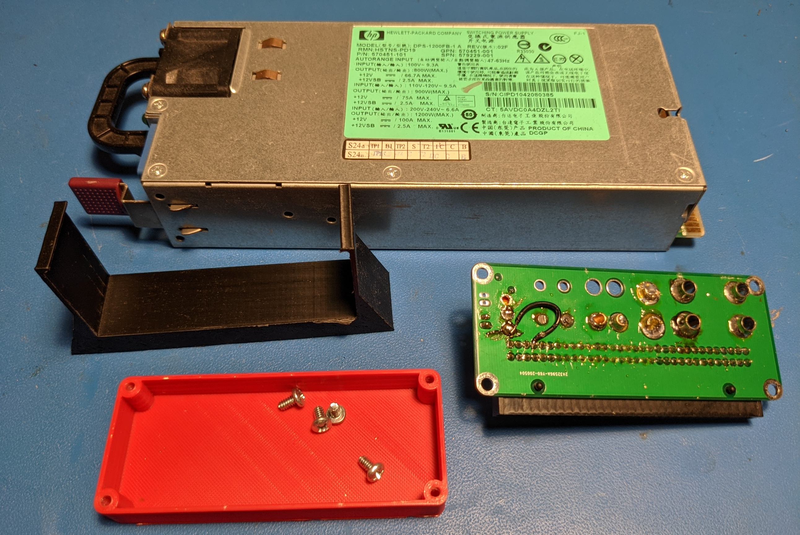
All Parts Disconnected
I made one mistake in designing this breakout board: I assumed that the supply conformed to the datasheet of a very similar supply made by Murata. That entailed grounding pin 33 to turn the supply on rather than connecting it to pin 36 as is commonly done by hobbyists.
Wrong pinout for the DPS-1200FB
So I modified the board to disconnect the ground side of the switch and to connect the previously floating side to pin 36. All of the design files at the top of the page correct for this mistake.
Correct connection to turn on supply

Bottom Side of Rev1 PCB Showing Mod