Geiger Counter
2022
SchematicLayout
Eagle Project
LTSPICE HV Supply Simulation
In 2022, Soviet surplus Geiger tubes could be purchased for $20, so I decided to finally get around to designing a Geiger counter circuit. The Geiger tube shipped to me from Kiev, Ukraine and was dropped of at a post office there on March 15 2022 — a time when Russian forces were advancing on the city on multiple fronts. Despite an active war, the Ukrainian post office was apparently still operating, and I received the package 18 days later. There are several decent open source Geiger counter designs online which were quite instructive, but the popular designs all use through hole parts and didn't really fit my style. I have always found surface mount parts to be significantly easier to use than through hole parts for hobbyist work (and in general), and I really like using the PCB as part of the enclosure for personal projects.
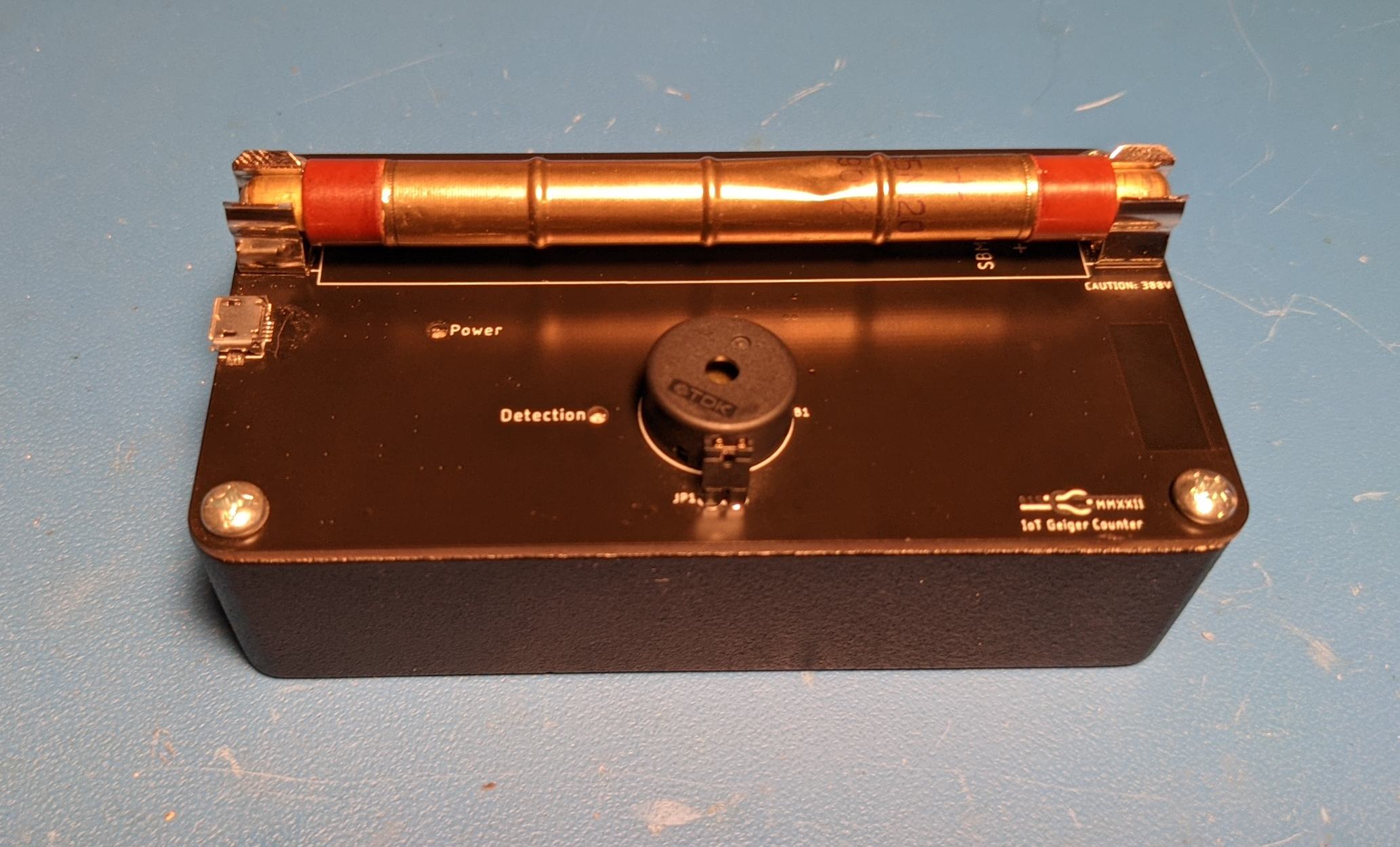
Finished Geiger Counter
After bulding the first revision, I made a few changes (most notably making the Geiger Counter battery powered) in a second revision.
Background
Geiger tubes are biased at a voltage high enough to allow for avalanche discharge. Single electrons are accelerated fast enough that they ionize additional gas molecules and make additional electrons (gas multiplication). UV photons spread the avalanche discharge down the length of the tube until the gas around the anode is completely ionized. This means that the output current pulse will have the same amplitude regardless of the energy of the incident particle. The bias voltage of proportional counter tubes is lower so that the energy spectra of incident radiation can be measured — there is still gas multiplication, but it is limited. On the low side of bias voltage, ionization chambers record the current from ion pairs created by the incident ionizing radiation itself without relying on multiplication effects.
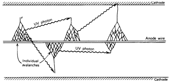
Avalanche Discharge in Geiger Tubes from "Radiation Detection and Measurement" by Glenn Knoll
The SBM-20 Geiger tube that I used is windowless and uncompensated. This means that it is more sensitive to beta and low energy gamma radiation than it is to high energy gamma radiation and that (because it is windowless) it is insensitive to alpha particles. I chose it because of its low cost and ubiquity, but there are better modern tubes available. High energy gamma photons are unlikely to interact with the gas in the tube, so it is actually secondary electrons created in the walls of the tube by interactions with gamma photons that set off avalanche discharge. To normalize the response of Geiger tubes over energy, compensation rings of thicker material can be added. In regions covered by the ring, beta radiation will be blocked and higher energy Gamma photons will interact with the ring to produce secondary electrons.
Geiger counters are best suited to measure low levels of radiation. After a Geiger discharge, it takes time for a tube to recover. The buildup of positive ions around the center anode is what stops the avalanche process from continuing indefinitely, and those positive ions in turn inhibit further discharges until they drift away from the anode. The time required for the positive ions to drift far enough for a second Geiger discharge to occur is called the dead time since ionizing events during this time cannot be counted. An ionizing event detected immediately after the dead time has elapsed will produce an output pulse, but its amplitude will be lower than the original pulse because the positive ions still present near the anode will contribute to stopping the avalanche discharge. The time required for these positive ions to drift to the cathode is called the recovery time.
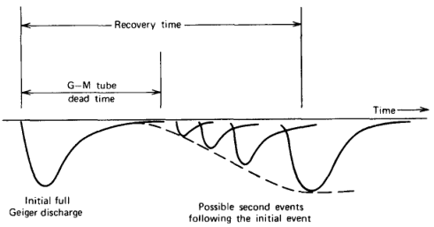
Dead Time and Recovery Time from "Radiation Detection and Measurement" by Glenn Knoll
The textbook "Radiation Detection and Measurement" by Glenn Knoll is an excellent reference for all things related to, well, radiation detection and measurement. The two above figures are borrowed from it. It lists the typical dead time of a Geiger tube as 50-100 µs. My bargain basement Soviet Geiger tube is a bit worse at 190µs if online translations of its Russian datasheet is to be believed. Assuming that a typical circuit can detect one event every 250µs, you could detect as many as 4,000 events per second or 240,000 counts per minute if the events are evenly spaced in time. The problem is that radioactive decay is entirely random, so you will start to lose accuracy at a much lower rate by missing events during dead time. Because an additional ionizing event resets the recovery time, events right after the dead time period are both missed and inhibit the detection of subsequent events for some period. The fact that observed counts decreases beyond a certain rate of ionizing events is called fold-back.
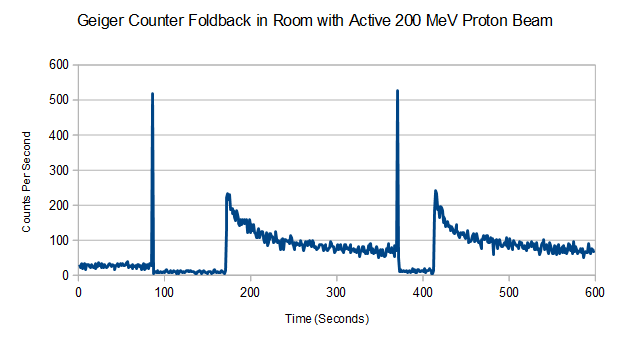
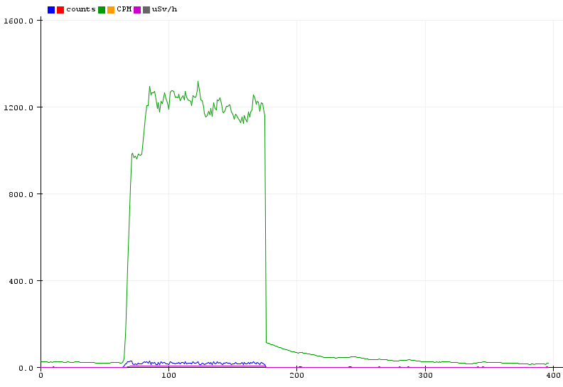
Geiger Counter Reading False Low Values from Intense Radiation
I placed this Geiger counter near the beam snout of a 200 MeV particle accelerator and easily observed fold-back when the beam was on. In the plot above, the beam was turned on twice: beam on can be identified by a sudden spike followed by a low count rate, and beam off can be identified by a jump in rate followed by an exponential decay. When the beam was on, the count rate was less than when the beam was off!
The datasheet for SBM-20 states that it has a working range of 0.014-144 mR/h, and the counting efficiency with Co-60 is 22 cps/mR/h. This implies a maximum count rate of 3168 which is in line with the calculation base on dead time and my own observations. With the Geiger counter in the same room as an active proton beam (but further away than in the previous plot), I observed a maximum count rate of 3294 CPS. The Geiger counter was right next to an activated lead brick as well which is why the base count rate is so high in this plot.
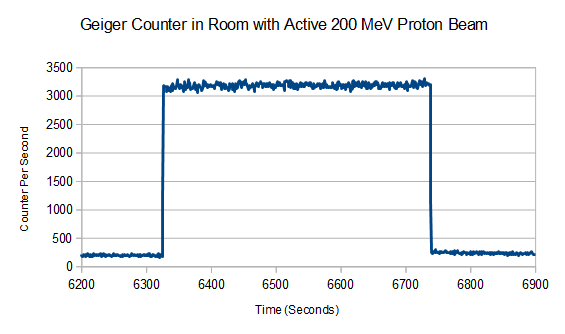
High Counting Rate From Active Proton Beam
3.6 Rontgen; not great; not terrible — since a typical Geiger tube is not good for more than a few hundred millirem, the 'dosimeter' referred to in the HBO "Chernobyl" series was likely an ionization chamber, not a Geiger counter. The other tell is that Rontgen is an air ionization unit with units of Coulomb per kilogram. One Rontgen deposits 0.96 rem (Rontgen Equivalent Man) in soft tissue, so speaking dangerously generally, Rontgen, rem, and rad are roughly equivalent. The modern definition of rem is rad multiplied by weighting factor, and the weighting factors of beta particles and gamma photons are unity. I have a CDV-715 Model 1A survey meter that I picked up years ago at a university surplus sale that is based on an ionization chamber. More than 6 million of this model survey meter were produced in the United States between 1962 and 1974, and its top range is 500 Rontgen/hour, so I guess I'm more prepared to assess the severity of a nuclear disaster than the Soviets in the 1980s.
Construction
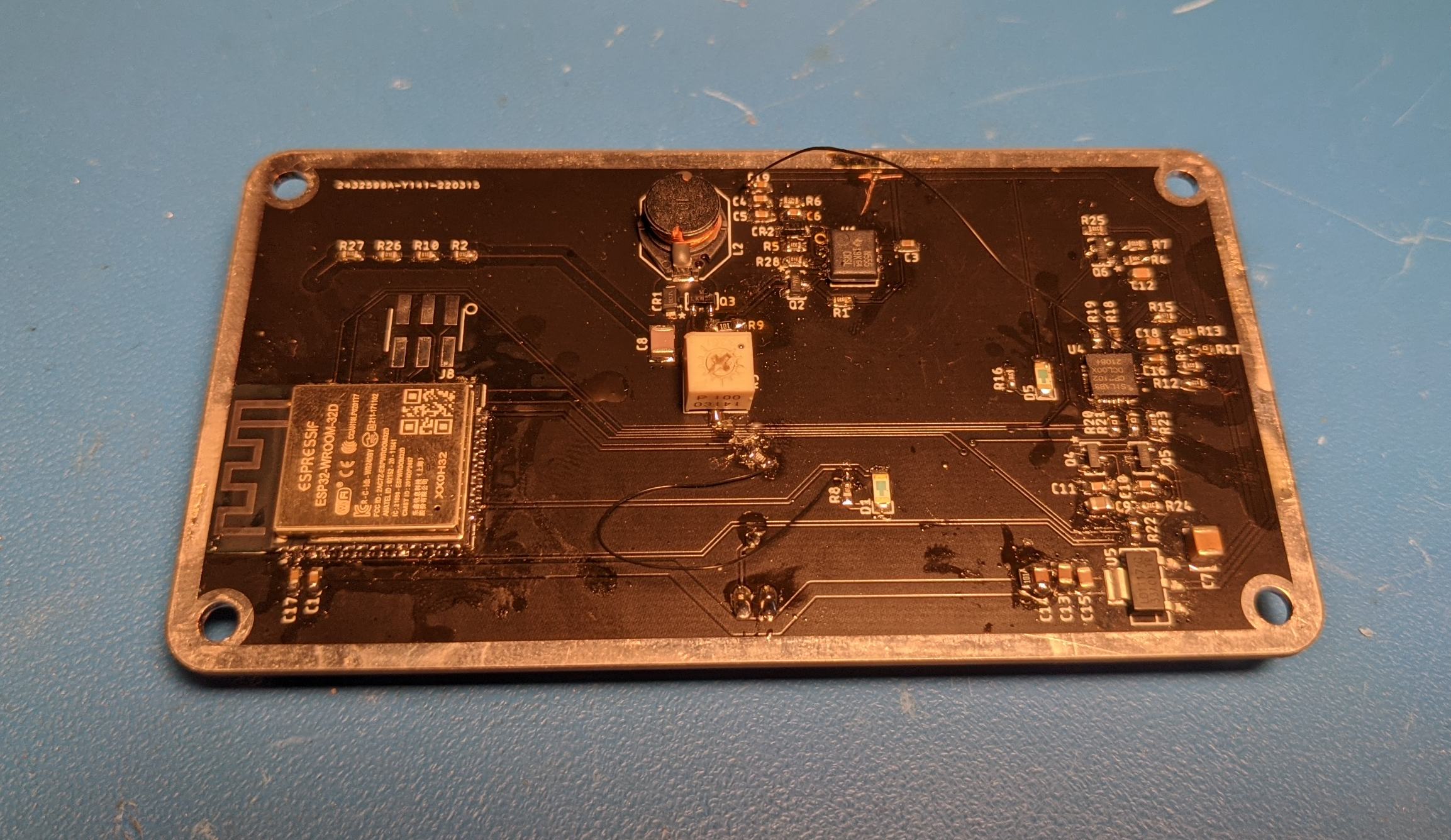
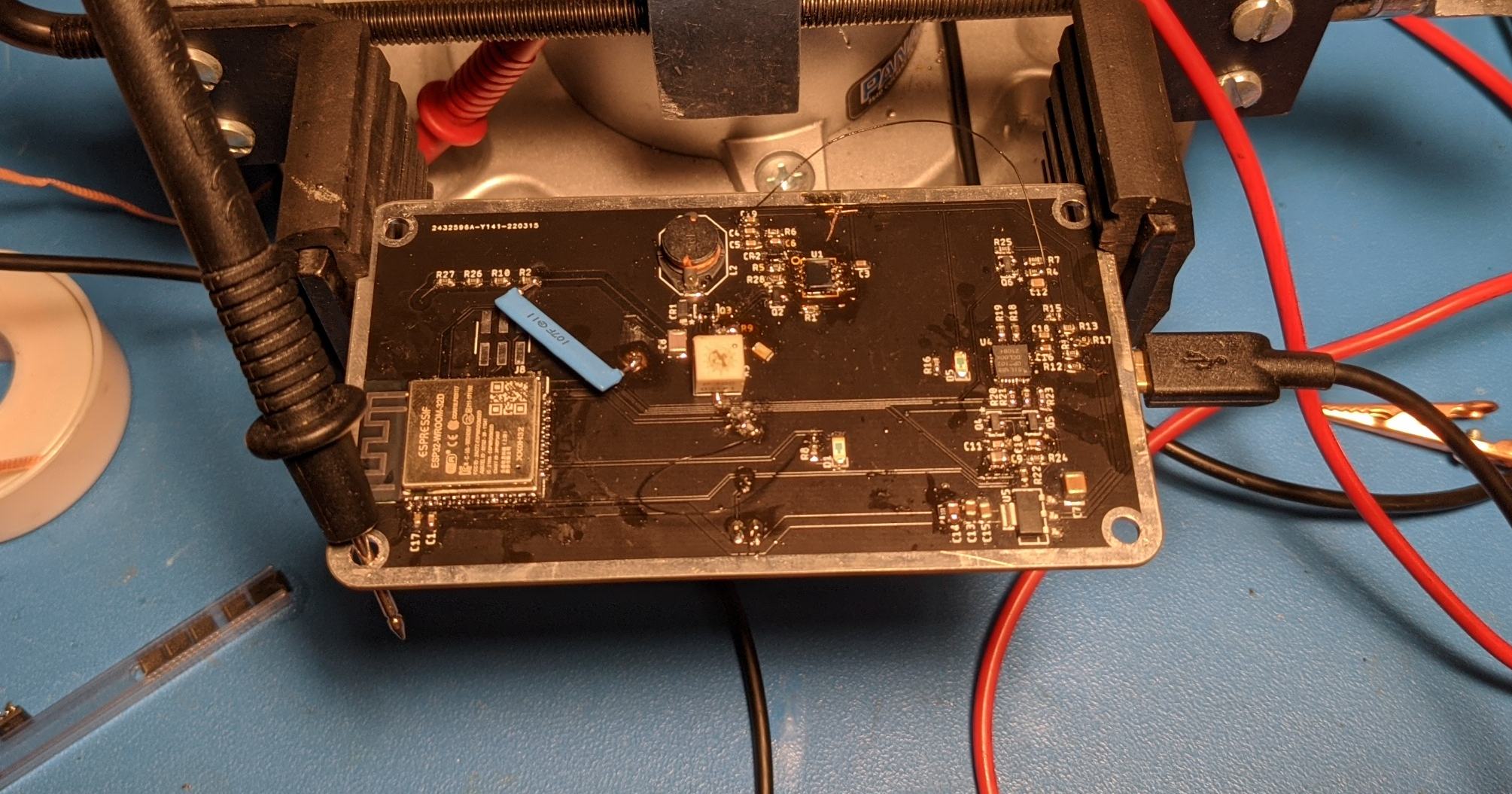
I used the same PCB-as-front-panel construction technique on this as I did on my picoammeter and random number generator. All active circuitry is on the bottom side of the board inside a Hammond 1590BBK aluminum enclosure. The PCB mounts directly to the top in place of the lid using standard 6-32 screws. I used surface mount fuse holders instead of through hole fuse holders because I would not have had sufficient clearance to the inside walls of the box with through hole parts. This fuse holder is actually intended for chassis mounted applications where it would be bolted into place, but it solders down as a surface mount part just fine.
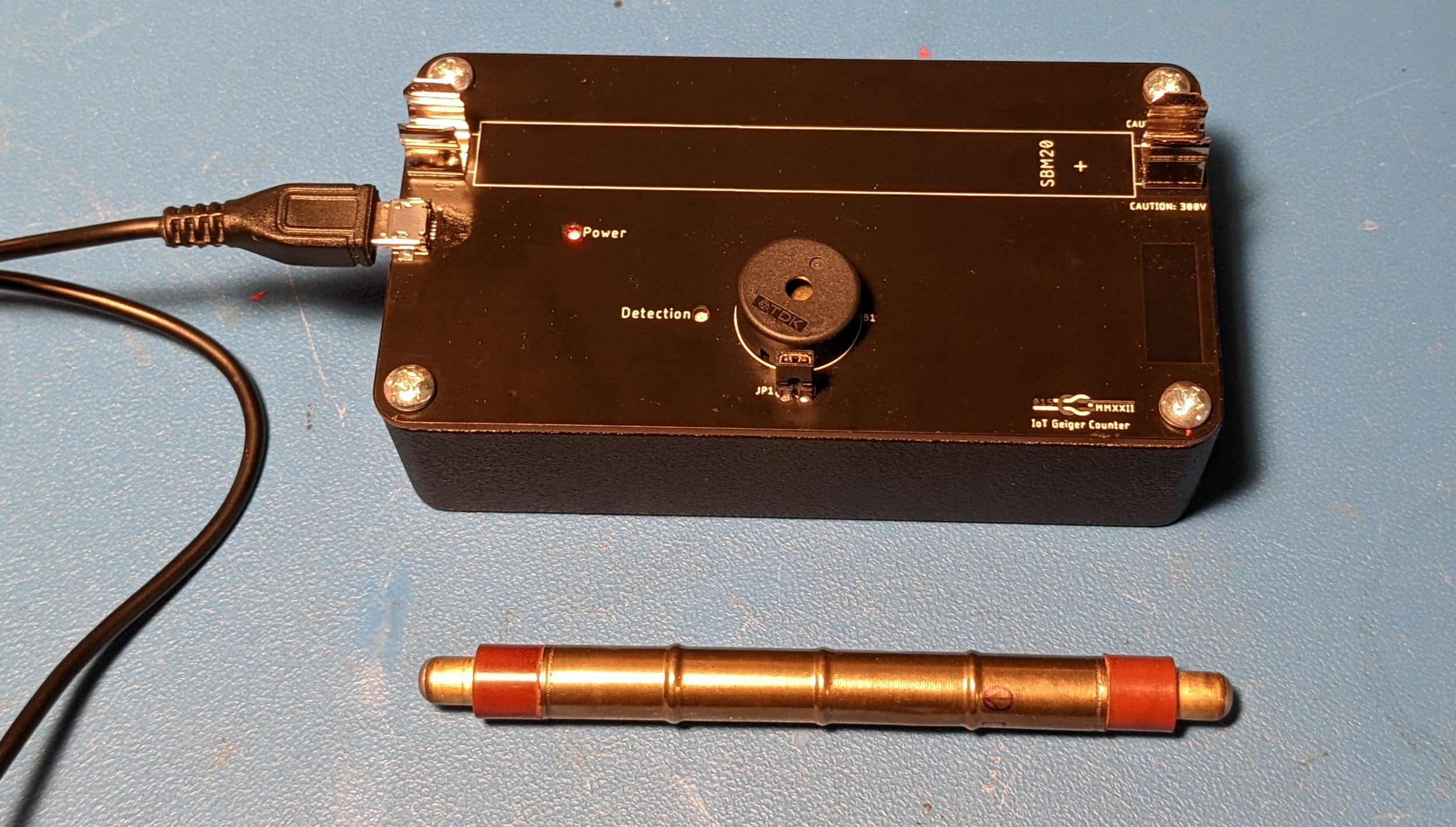
Geiger Counter Assembly
The LEDs are reverse mounted over holes in the PCB which allows their light to shine through from inside the box. The box is powered from a micro-USB connector at the left edge, and there isn't a power switch since it isn't battery powered. The jumper next to the Piezo buzzer is in series with it allowing it to be muted when the jumper is removed. The rectangle of missing top copper on the right of the PCB is to allow 2.4 GHz to pass through to the WiFi antenna on the ESP32 module inside the box.
Despite there being 400V on the Geiger Tube, the 4 MΩ of current limiting resistors limits current to only 100uA which is well under the 1mA limit for sensation by the human body, so it is safe to have the tube exposed on the outside of the box where you can touch it — shorting across the tube with your hand does allow enough current to flow to trigger a false detection, though, which is handy for testing.
Circuitry
There are three basic parts of a Geiger counter circuit: a high voltage power supply, a pulse detector, and a circuit to convert pulses into a rate reading.
Board Before Replacing 555 Timer with High Speed Variant
High Voltage Power Supply
I considered using a voltage multiplier circuit driven by an integrated switch boost converter here, but after simulating, I decided to stick with the 555 timer based circuit from the Mighty Ohm Geiger Counter design. This circuit relies on the fact that a boost converter in discontinuous conduction mode can have a very high conversion ratio with a relatively low duty cycle and that, for a fixed load, output voltage of a boost converter in DCM is dependent on inductor stored energy.
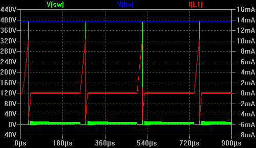
Discontinuous Mode Boost Converter from Simulation Below
A boost converter in continuous conduction mode (current through inductor does not go to zero at any point during a cycle) has a conversion ratio of Vout=Vin*1/(1-D), so a converter with an input voltage of 5V and a duty cycle of 75% will have an output voltage of 5*1/(1-0.75)=20V. If the converter is in discontinuous mode, output voltage is dependent on the energy stored in the inductor when the switch is on and the per cycle losses. Assuming a 10kHz switching frequency, a 5V input, a 10mH inductor, and a 50% duty cycle, the energy stored in the inductor per cycle is \(E={{1}\over{2}}LI^2={{1}\over{2}}0.01*{{5*0.5}\over{0.01*10000}}^2=3.12µJ\). The per cycle losses are from the load on the output (only leakage current in absence of events) and from switching losses which are frequency and voltage dependent. So even with no load, there is a certain maximum voltage you'll hit for various inductor energies due to energy lost in the transistor and diode. Operating a boost converter in discontinuous mode means that the inductor is not being used particularly efficiently, but with extremely light loads like Geiger counters, this doesn't matter because the loaded efficiency of the circuit is basically irrelevant: only the quiescent current draw matters since that will always be far greater than the draw of the tube.
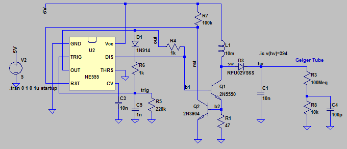
LTSPICE Simulation of High Voltage Supply
The 555 timer controls output voltage by regulating the peak current through the inductor. The 555 timer enables its output which turns on Q1 when the trigger voltage falls to VCC/3. It disables its output and turns off Q1 when the voltage across the sense resistor R1 exceeds the ~0.6V threshold voltage of Q2. This happens because Q2 pulls down the reset pin of the 555 timer. This is not a fixed frequency controller; only the off-time is fixed. The whole time that the output is enabled, the trigger cap is kept charged. I'll also say that I had trouble getting the circuit to regulate to a low enough voltage. On first power up, though I didn't know it at the time, I was generating over 600V.
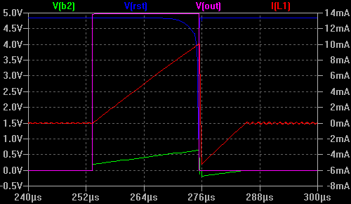
LTSPICE Simulation of High Voltage Supply
The fact that the output voltage is load dependent combined with the load of the Geiger tube being so small means that probing the output with a typical 10 MΩ multimeter will significantly change the operating point. To get around this, I placed a 1 GΩ resistor in series with the positive lead of the meter. To calibrate this setup, I used two meters. One with the 1 GΩ resistor and one without. When both meters were connected, I measured 252 V on the directly connected meter and 2.72 V on the meter with the 1 GΩ resistor. I also disabled auto-ranging just in case meter input impedance is range dependent. At this particular range, the input impedance of the meter was apparently 10.91 MΩ. After disconnecting the meter with no series resistor, the voltage shot up to 6.41V which corresponded to 594V! Adjusting the current sense potentiometer to its max range of 15Ω brought the voltage to an acceptable 450V. I was initially not successful at getting the voltage any lower regardless of low side resistance. This because I was using a standard speed 555 timer and not a high speed 555 timer. There was a noticeable delay between the assertion of reset and the switch actually turning off, resulting in minimum on-time issues.
After replacing the 100kHz 555 timer (TI SA555DR) with a 21.MHz 555 timer (TI TLC555IDG4), I was able to adjust the output to exactly 400V
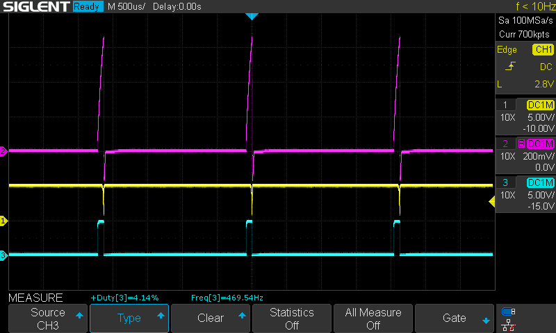
Measured Waveforms with TLC555IDG4. Pink = Sense Resistor Voltage, Yellow = Reset, Cyan = Output
I saw pretty funky waveforms with SA555DR wit higher current sense resistor values, but TLC555IDG4 nicely regulates to proportionally lower voltages with proportionally higher sense resistor values as it should.
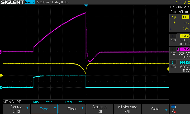
Detailed Measured Waveforms with TLC555IDG4. Pink = Sense Resistor Voltage, Yellow = Reset, Cyan = Output
With a high speed 555 timer, the measured waveforms closely track the simulated waveforms. I also noticed that even with the 1 GΩ series resistor I was seeing the output voltage droop when probed. To get around this issue and to guarantee a more stable output voltage over load (thus ensuring a more stable output voltage in higher radiation environments), I added a 100 MΩ load resistor and adjusted the output voltage to 400V with that resistor in place.
Rather Crusty Board After Many Reworks
One thing to note is that the only 'voltage reference' in the system is the threshold voltage of Q2. Since this is temperature dependent, the output voltage will also be temperature dependent. While the output voltage is 400V at 25C, it is 480V at -25C and 350V at 50C. The plot below shows a simulation at -25, 0, 25, and 50C. A weather balloon carried one of these Geiger counters and started reporting a very high count rate at 20km altitude. It certainly could have been acring across the tube due to low pressure, 20km altitude is a local minimums of atmospheric temperature. Assuming the Geiger counter got to -65C, the anode voltage would have been 575V which certainly would have contributed to arcing (but for a SBM-20 probably would not have caused spurious discharges)
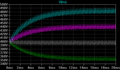
Temperature Dependence of the High Voltage Circuit
Pulse Detection (Discriminator)
This Geiger counter counts events by detecting current pulses from the cathode of the Geiger tube to ground. This makes things pretty simple: all you need is an NPN BJT. This is, however, not the normal way that this is done. Consider that a probe separate from the Geiger counter and connected by a coaxial connector will need to either bias the shield to high voltage (possible acceptable if the case of the counter is biased at the same voltage), or the return current along the shield will need to be measured which means that it cannot be bonded directly to the case of the meter. In order to put high voltage on the center conductor, the current into the tube needs to be measured. This can be accomplished by AC coupling the anode to the discriminator circuit after the large resistors to the high voltage supply. If I make a second Geiger counter, it will use this method so that I can support BNC connected external probes.
I have not extensively tested this circuit to see how sensitive it is. It obviously works for typical pulses, but I don't know what the limit is for the reduced amplitude pulses expected from ionizing events received after the dead time has elapsed and before the tube as fully recovered.
Counting
I used the pulse counter (PCNT) module of an ESP32 to count the Geiger discharges. It reports once per second the number of pulses recorded in the previous second. That raw signal is then filtered with an exponential averaging function to provide a less noisy average count. I implemented a half-baked function that varies the alpha factor of the exponential averaging function based on how far the last count is from the running average. A straight exponential average that yields reasonable results for typical background rates will take many seconds to settle reasonably when the Geiger counter is taken into or brought out of a high radiation environment. Instead, if the rate in the last second is twice that (or half that) of the running average, the alpha factor is increased proportionally to the difference. This seems to work reasonably well for the kind of toy applications I have for the counter.
To test the response of the averaging code without actually exposing the tube to a high radiation environment, I found that I could simulate one by sorting out the tube with my hand and lightly sliding one finger across one of the contacts.
In addition to counting pulses, the ESP32 also flashes an LED and chirps a piezo buzzer for 2 ms. I picked the tone D7 since it sounded the most like traditional Geiger counters to me. In high radiation environments with significantly more than 500 CPS, the tone becomes uninterrupted (up until saturation when detected counts decrease, that is). Since the clicking can get a bit annoying, I wired the piezo buzzer in series with a two-pin header shorted by a jumper. To silence the buzzer, you can remove the jumper.
Serial Output From Thorium Dioxide Source Plotted With Arduino Serial Plotter
The result is sent over the USB virtual serial port, but since this is an ESP32, I can trivially change the code to make it an actual IoT Geiger counter. I'm prepared for the next Fukishima at least. I'm looking forward to saying "No, guys, its actually fine."
Support Circuitry
I basically duplicated the power and serial parts of the ESP32-DEVKITC-32E design. This was built at the height of the Great Parts Shortage, so I ended up de-soldering a CP2102N USB to serial chip off of an ESP32 development board since they were not in stock at any distributors. 3.3V is generated by a standard linear regulator since there is no reason to try and save power when you have a USB input. I often power the Geiger counter using a USB On The Go adapter from my phone, but if I build a second version it will be battery powered.
Issues
Aside from the voltage regulation issues arising from using a standard speed 555 timer, I also had issues getting the ESP32 to accept programming. I messed up two things: IO2 pin strapping and enable timing. These were easy enough to resolve, though. I just bodged in a pull-down resistor on IO2 and added a 10uF ceramic cap to the enable line. After making those changes, I was able to program the board normally using the Arduino IDE.