Magnetics Calculator
2022
I couldn't find a guide to designing toroidal transformers using typical datasheet characteristics like \(A_e\) and \(l_e\) that derived its equations from first principles. I dislike using equations with magic numbers in them, so I brushed up on college physics and put this together.
This calculator provides magnetizing inductance and volt-microsecond product which are useful for transformer design. Frequency and drive waveform are used to calculate the input voltage required to saturate a transformer. This calculator also works for inductor design (magnetizing inductance = inductor inductance), and because it is based on effective core characteristics, it also works for core shapes other than toroids when \(A_e\) and \(l_e\) are available.
Calculator
Definitions
- \(A_e\): Effective magnetic cross-section.
- \(A_L\): Inductance factor: \(A_L=L/N^2\) where L is customarily expressed in nH. A ten turn winding on a core with an \(A_L\) of 1000 will have an inductance of \(L=A_LN^2=1000\cdot10^2=100,000nH=100uH\)
- \(B\): Magnetic flux density with SI unit Tesla (T). (B = Wb / m^2)
- \(B_{sat}\): Magnetic flux density where a core material begins to saturate.
- \(ET\): Voltage-Time product. Often expressed in volt-microseconds. Time that 1V can be applied to a particular transformer winding before it saturates.
- \(H\): Magnetic field strength. SI units of A/m.
- \(I\): Current (A) through the primary winding.
- \(l_e\): Effective magnetic path length.
- \(N\): Number of turns of the primary winding.
- \(Φ\): Magnetic Flux with SI unit Weber (Wb). Integral of B field over a particular area.
- \(μ\):Permeability. The ratio between magnetic flux density and magnetic field strength.
- \(μ_o\):Permeability of free space equal to \(4π\cdot10^{-7} H/m\)
- \(μ_r\): Relative permeability. The ratio of the permeability of a material to the permeability of free space.
Derivation of Equations
While the length and area inputs of the calculator are in centimeters, all of the following equations are in SI units (meter, Tesla, Weber, second). The calculator converts to meters internally.
Flux Density and Inductance
Toroid Illustration from Rose Hulman
Flux density in a toroidal core can be derived using Ampere's law:
\[∮_cB\cdot dl =μI_{enc}\tag{1}\]The path of the contour integral is through the center of the toroid. Effective magnetic path length as stated in core datasheets is a value close to \(2πr\) where r is the radius of revolution of the toroid. Since B can be assumed to be constant in the core, the integral turns into multiplication. \(I_{enc}\) is the current enclosed by the contour integral. Since the path of the integral is through the center of the core (black dashed line), the enclosed current is equal to the number of wire turns (number of times that the wire passes through the annulus of the core) multiplied by the current through the winding. Additionally, as the core is made of a core material and not vacuum, \(μ\) is used instead of \(μ_o\).
\[B=\frac{μNI}{l_e}\tag{2}\]The flux in the core is equal to the flux density (B) multiplied by the area of the core. Here I am using effective area which compensates for the fact that the core is not 'thin.' Because most cores are physically small, the flux density at the outer edge of the core will be somewhat lower than at the inner edge of the core. By using a datasheet effective area value (if one is available) you don't have to worry about this.
\[Φ=\frac{μNIA_e}{l_e}\tag{3}\]The definition of inductance is:
\[L=\frac{NΦ}{I}\tag{4}\]This is in units of Henries. When this is combined with equation (3) you get:
\[L=\frac{NΦ}{I}=\frac{μN^2A_e}{l_e}\tag{5}\]Expressed in relative permeability, this is:
\[L=\frac{μ_oμ_rN^2A_e}{l_e}=\frac{4πμ_rN^2A_e}{l_e}\cdot 10^-7\tag{6}\]Time for a quick spot check. The datasheet for B64290L0038X038 states that the core has the following characteristics:
- \(l_e=24.07\text{ mm} = 2.407\cdot10^{-2}\text{ m}\)
- \(A_e=7.83\text{ mm}^2=7.83\cdot10^{-4}\text{ m}^2\)
- \(μ_r=10,000\)
- \(A_L=4090\text{ nH/T}^2\)
So, if the inductance of a single turn winding is calculated using equation (6), the result should be 4,090 nH.
\[L=\frac{4πμ_rN^2A_e}{l_e}\cdot 10^-7=\frac{4π\cdot10000\cdot1\cdot7.83\cdot10^{-6}}{2.407\cdot10^{-2}}\cdot 10^-7=4.087\cdot10^{-6}\text{ H}=4090\text{ nH}\]How about that? Truncated to three significant figures, it is exactly the correct answer.
Volt-Second Rating
Pulse transformers can be compared by their volt-microsecond ratings. That is, the number of microseconds that 1V can be applied to the primary winding before the core saturates. It is the product of volts and microseconds that matters: a 25 Vµs transformer will saturate after 5V is applied for 5 µs. This rating can be derived from Faraday's law:
\[E=N\frac{dΦ}{dt}=NA_e\frac{dB}{dt}\tag{7}\]The volt second rating is equivalent to how long it takes 1V applied to the primary winding to go from one extreme of saturation to the other, stated differently, when you apply an AC voltage to a transformer or inductor, the core is driven to both positive and negative points on its BH curve:
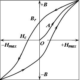
Typical Hysteresis Curve of a Soft Saturating Material with Low μ
The ΔB required to take the transformer from negative saturation to positive saturation is equal to two times \(B_{sat}\). Volt second ratings are based on this swing in B with an assumed square wave drive voltage. Note that I am able to substitute \(ΔB\) for \(dB\) here because dB is constant with a square wave drive voltage.
\[E=N\frac{dB}{dt}=NA_e\frac{ΔB}{Δt}=NA_e\frac{2\cdot B_{sat}}{Δt}\tag{8}\]\(ΔB\) is equal to two times \(B_{sat}\) because the core is going from negative to positive saturation. Rearranging to solve for volt-seconds and you get:
\[E\cdot dt = V \cdot s = 2\cdot NA_eB_{sat}\tag{9}\]Volt microseconds can be found by multiplying this number by \(10^6\):
\[V \cdot µs = 2\cdot NA_eB_{sat}\cdot 10^6\tag{10}\]Equation (9) can also be re-arranged to calculate the maximum drive voltage for a square wave input of a particular frequency. Half the period of the square wave is used because that is the time the waveform spends at a particular voltage:
\[V_{max} = \frac{1}{0.5\cdot period}2\cdot NA_eB_{sat}=4\cdot fNA_eB_{sat}\tag{11}\]This method can also be extended to cover sinusoidal drive voltages. Starting with Faraday's law:
\[E=NA_e\frac{dB}{dt}\tag{12}\]B is sinusoidal with a max value (for the purposes of finding maximum voltage / minimum frequency) of \(B_{sat}\). \(\frac{dB}{dt}\) can be found by taking the first derivative of \(B_{sat} \cdot sin(2πft)\)
\[\frac{dB}{dt}=2πfB_{sat}cos(2πft)\tag{13}\]By solving for peak voltage, I can drop the cosine term:
\[V_{pk}=\sqrt{2} V_{rms}=NA_e2πfB_{sat}\tag{14}\]Rearranged, you get:
\[V_{max(RMS)}=\frac{2π}{\sqrt{2}} \cdot fNA_eB_{sat}=4.44 \cdot fNA_eB_{sat}\tag{15}\]4.44 is one of the 'magic numbers' that I sought to find the origin of.
Saturation Current
The saturation current for a given winding is calculated by simply re-arranging equation 2:
\[I_{sat}=\frac{l_e B_{sat}}{μN}\tag{16}\]