Western Interconnect Grid Data
2022
Arduino IDE Code for ESP32While designing my grid frequency meter, I realized I could add an ESP32 development board and log the measurements to my web server pretty easily. I connected the ESP32 to the GPS serial interface for time of day information and to the STM serial interface for measurement data. My custom board sends a message once per second 0-50 ms after the start of a second, so the ESP32 waits to receive both the message from the STM32 and the GPS NMEA message and then sends an HTTP POST request to my server containing that formatted data and an API key. I mostly followed this tutorial for setting up the server side stuff.
A PHP script on the server saves this data to a MySQL database, and when this page is loaded, a different PHP script pulls the last 24 hours of data from the MySQL database. This is graphed using a lightweight javascript library called dygraphs. Dygraphs works great on desktop, but it doesn't do a great job with fine pinch zoom on mobile.
Update 9/5/24
Well, a MySQL server maybe wasn't the most efficient way to implement this. Given the small number of measurements, I think a flat append-only file would have worked just fine. I also probably would have used a MQTT server as an intermediary rather than using PHP with HTTP POST. The log file for my web server is clogged with entries for the frequency meters, and because I use an embarrassingly cheap VPS to host this website, I have to go in periodically and delete the MySQL database when I run out of disk space.
If you notice a step discontinuity in the time deviation graph and a period of missing frequency data, it is because I lost GPS lock due to poor placement of the Western Grid antenna in my new condo.
Update 11/15/25
I have upgraded the grid frequency meters to use only ESP32s and have switched to MQTT. The graphs on this page are no longer functional.
Data
The box in bottom left is the adjustable rolling average window in seconds. The display can be rest with a double click.
Time deviation is accumulated frequency error. When a rising edge of the AC line is detected, a counter variable is incremented. When a rising edge of GPS PPS is detected, 60 is subtracted from the counter variable. The time deviation shown here that counter variable divided by 60. This is identical to the difference in time you would see on a clock driven by a synchronous AC motor and GPS time over the same interval.
Wifi Antenna
Since I only have SMA bulkhead connectors and WiFi antennas are normally RP-SMA, I made an antenna using a piece of semi-rigid coax. I tripped back a random length of the shield and then trimmed back the inner conductor until its point of resonance lined up with 2.4GHz. I confirmed this using a NanoVNA V2 Plus. I bought this for around $100 a few years ago, but I would say it would be a steal at twice the price. They discontinued the V2 Plus model and introduced V2 Plus4 which has a larger screen and a metal case for $200. I'd still recommend this since the alternatives are eBay knockoffs or $1000+ units from more established manufacturers.

Antenna Tuning Setup
I like to test antennas on a metal plate like this so that I have a good ground plane and to keep the antenna fixed — the response of antenna on a length of coax alone can be a bit squirrelly especially for antenna like this with no sleeve balun.

Antenna S11
I trimmed the antenna very slightly too high, but after sliding a 3D printed sleeve over the antenna, the frequency is right where I want it.

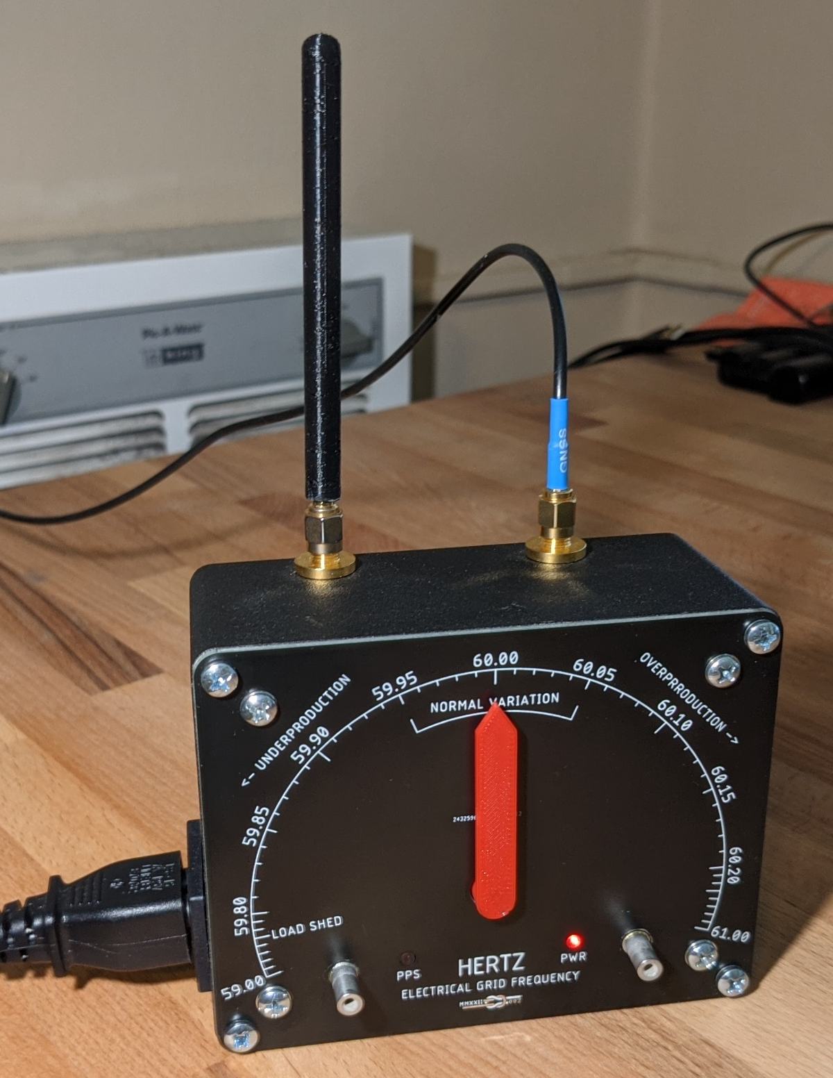
Assembled Meter with Added WiFi Antenna for Logging Through ESP32