70CM SAW Filter + LNA
2024
I was transmitting LORA at 433MHz last year through a pretty big amplifier. While I could pick up the signal across teh city in some cases, I was only barely able to pick it up at my friends's roof eight blocks away which made little sense given the power I was transmitting at. I realized that my friend's roof was in direct line of sight with several transmitting towers carrying FM radio, digital TV, microwave links, etc: The SX1262 reported a strong signal but poor SNR which made me realize tha the front end of the transceiver was likely getting overwhelmed. Solution: add a SAW filter to the receiver to reject everything except for the desired band.
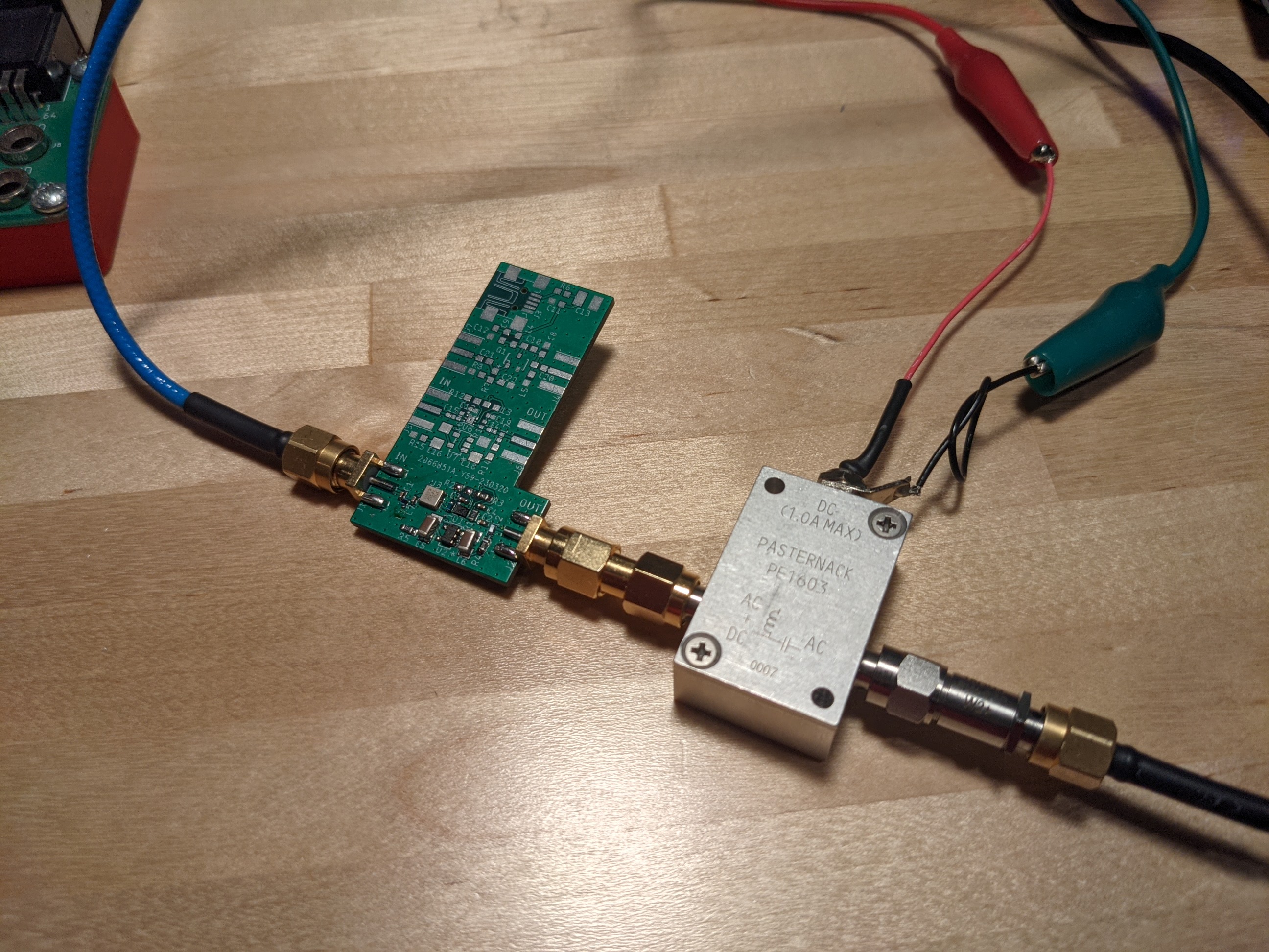
Filter PCBA with Bias-T and 20dB attenuator
The input third order intercept for SX1262 is -5dBm, so you will see some gain compression and noise figure degradation even at -15dBm. So if you're in an RF quiet area, you don't need a filter, but if you are in a noisy area with strong transmitters, you may benefit from a filter.
Design
I chose a 433 MHz filter (B39431B3710U410) because it was commercially available and because 433 MHz is in the US 70 cm band (420-450 MHz). This is a pretty narrow filter (433-434.71 MHz) design for remote control receivers. While writing up this project, I found a filter with better coverage of the 70 cm band: TA0419A. This filter is specified from 431.5-450.5 MHz which covers most of the 70 cm band. The insertion loss of both of these filters is around 2 dB which of course reduces the sensitivity of the receiver, but that is the price you have to pay to attenuate out of band blocking signals.
For the LNA, I went with a reasonably priced, low noise figure and low bias current option that I thought would be alright to solder: BGB741L7ESD. I was wrong. This part ended up being a huge pain to solder because its pads don't have wettable flanks. That means that the only solderable area on the pads is under the part making rework with a soldering iron (the way you can normally clean up QFN and DFN solder joints if initial reflow wasn't perfect) impossible. It took me several reflow attempts and much cursing to get it to work.
I also chose this part because of its low P1dB (output power at 1dB gain compression) — The absolute max RF input power to SX1262 is +10dBm, so having an LNA P1dB at least 3 dB below that will protect the transceiver from the LNA driving an overly powerful signal into it. Many of the other low noise figure LNAs on Digikey have rather high P1dB ratings. If I did this again, I would probably take the noise figure hit and use a part like BGA420H6327XTSA1 — or just have JLCPCB do the assembly since they have BGB741L7ESD in stock.
The board is powered through a bias-T to allow it to be located at an antenna and powered through the transmission line back to the receiver. a TPS76133DBVR LDO provides regulated 3.3V to the LDO. The board uses a four layer stackup with decent edge launch SMA transitions. I included a couple other designs on the board since its basically free to use a bit more PCB space when you're under the JLCPCB deal limits.
Result
After finally getting the LNA soldered down, I got pretty good results:
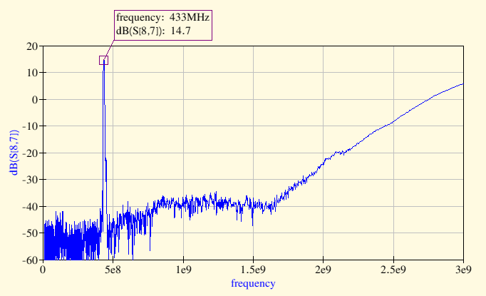
Wideband Response of Filter + LNA
These measurements were taken with a NanoVNA controlled from my desktop using NanoVNA-Saver. I added a 20dB attenuator to protect the NanoVNA and added that exernal attenuation as an offset. Focusing in on the passband shows a 3dB bandwidth of 7 MHz:
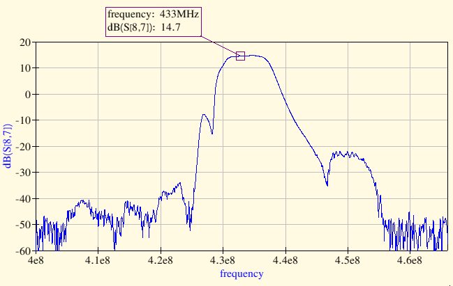
Narrow-Band Response of Filter + LNA
As expected, with this filter I had far better performance using 433 MHz LoRa in a city.