Continuously Variable Slope Delta (CVSD) Modulation
2023
DNVTs encode audio using Continuously Variable Slope Delta Modulation (CVSD) which is a variant of Delta Modulation. In Delta Modulation, a digital high or low indicates that the output of the demodulator should step up or down by a fixed value. In CVSD, the slope (e.g. the amount by which the demodulator should change) increases when some number of consecutive ones or zeros is detected. This allows for a higher dynamic range: in delta modulation, you have to decide between whispers being below the quantization level and shouting clipping. With a variable slope, shouting causes the slope to increase to avoid (until a maximum slope value is reached) clipping. This is analogous to companding in Pulse Code Modulation (PCM). There are three benefits of CVSD that lend to it being used by the DNVTs: it requires no framing (it is encoded as a continuous bitstream), it is tolerant to moderate bit error, and it is easy to implement using analog circuitry.
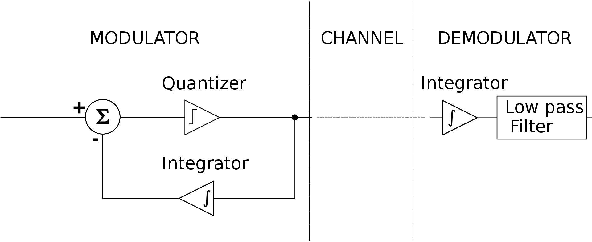
Delta Modulator Block Diagram by Katanzag
A Delta modulator consists of both a modulator and a demodulator. The audio signal to be encoded is compared to the locally demodulated bitstream. If the current value of the demodulated signal is less than the input audio, the modulator outputs a 1 and if the audio is less than the demodulated signal, it outputs a 0. Silence is encoded as 0101 repeating: the demodulated signal with dither around the desired value. The demodulated signal is low-pass filtered to remove this high frequency noise before the amplifier that drives the speaker in the receiver headset.
It is not necessary to decode CVSD audio to build a switch for multiple DNVTs since you can directly shuffle bits from one phone to another. You do need to decode CVSD if you want to interface a DNVT to something other than a DNVT such as an Asterisk server connecting to the Public Switched Telephone Network (PSTN).
DNVT Analog CVSD Implementation
CVSD encoding and decoding in DNVTs is handled by Motorola MC3517 integrated circuits. These chips implement the general block diagram shown above with the addition of a three-bit shift register and a circuit which detects coincidence of the three bits. When coincidence is detected, the chips varies its gain by driving a "syllabic" filter driven by the coincidence output. Said another way, when three consecutive ones or zeros are detected, the demodulator increases its gain.
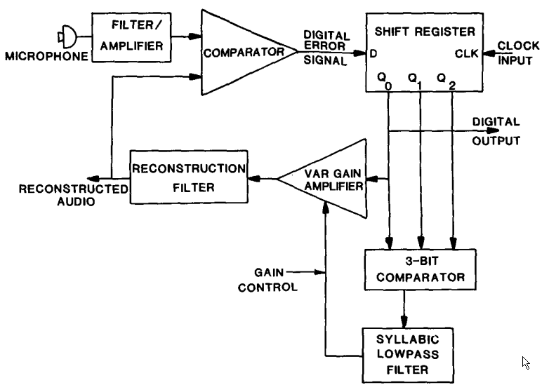
DNVT Encoder Block Diagram from IEEE Paper
The same blocks are used when the chip is used as a demodulator: instead of using the demodulated signal as feedback for the encoder, the demodulated signal is filtered and presented to the user.
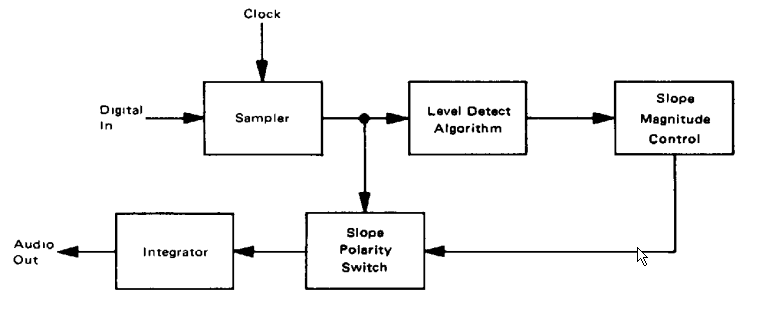
MC3517 Decoder Block Diagram
As with any analog to digital converter, you want to attenuate frequencies above the sampling rate so that energy at these frequencies does not cause aliasing in the passband. This is implemented with an active low-pass filter which, according to the IEEE Paper is implemented in DNVTs with a 70-3500 Hz bandpass filter with a 12 dB/octave roll-off. On the receive side, you want to attenuate quantization noise. Since the input is filtered above 3500 Hz, any energy at frequencies above that can also be safely attenuated at the demodulator. The IEEE paper indicates that the DNVT output filter is a 5th order elliptic lowpass filter with a 3400 Hz cutoff. In practice, this filter is a bandpass which does not pass DC; I've observed that there can be as much as 1% imbalance between received ones and zeros on audio encoded by a DNVT. Without high pass filtering of some sort at the receiver, the audio will quickly saturate. While this I did not trace out the exact circuitry in the DNVTs, the example circuit in the MC3517 datasheet shows a leaky integrator which takes care of any DC build-up.
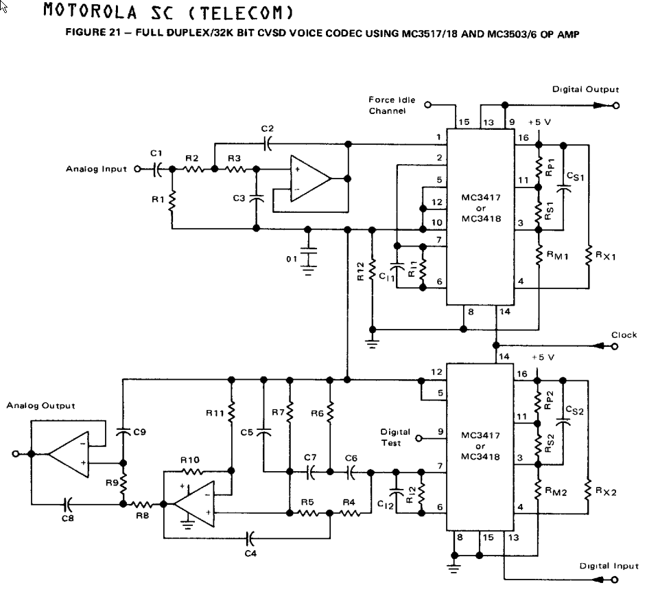
Full Duplex CVSD Encoder / Decoder Similar to Circuit in DNVTs
Decoding CVSD in Python
To decode CVSD without distortion and without artifacts, you need to make some guesses at the filter coefficients and gains used in the DNVTs. As a first pass, Nick threw together a quick python script that converted hex encoded DNVT data into a 16-bit WAV file using delta modulation (constant gain per bit). Though rather distorted (especially evident on the PTT tones), the result was intelligible. As an aside, the DNVTs have a push-to-talk (PTT) switch which transmits a CVSD encoded 1231 Hz tone for 500 ms when pressed and a 1455 Hz tone when depressed. These tones can be used to control radio transmitters: 1231 Hz tones signal that the radio should switch to transmit and 1455 Hz tones signal that the radio should switch back to receive. These tones were proved handy for ferreting out sources of distortion in the modulating and demodulating code.
Over Thanksgiving, the two of us iterated on the Python script to produce a higher fidelity decode. To support this, I added some graphing to the script to show gain and number of coincidences. With much iteration, I eventually arrived at a minimum gain of 100, a gain step per coincidence of 30, a maximum gain of 18000, and a gain decay of 0.99 per sample. To correct for the imbalance of ones and zeros, I multiplied the demodulated signal by 0.96 on each sample. Smaller gain steps provide more dynamic range at the expense of fidelity at lower amplitude. Shouting still causes signal clipping, but that matches the qualitative result from listening to a phone with someone shouting on the other end.
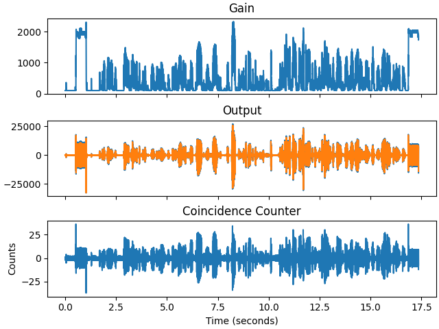
Gain, Demodulated Output (Exponentially Averaged), and Detected Coincidences of Reference Capture
The initial decoding script output 8 kHz sampled PCM which due to poor filtering prior to this resampling reduced the quality of the output. After changing the script to output at 32 kHz, I added a simple three-step exponential average to remove the undesired high frequency content from the output signal and got a half-way decent result.
Exponential averaging is computationally simple, but it distorts the audio. The PTT tones of the phone look more like triangle waves than sine waves. Nick changed the filtering to an IIR, and we finally had a decoding script with minimal distortion.
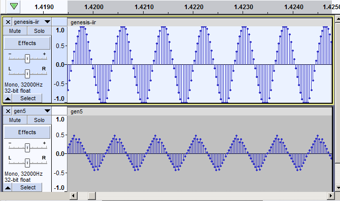
Comparison of Exponentially Averaged (Bottom) and IIR Filtered (Top) Audio
Encoding CVSD in Python
To encode audio as CVSD, you must first have a functioning decoder since the encoder determines its output by comparing the input audio to a decode of its CVSD encoded audio on the fly. The graph below shows the encoder's input, feedback decode, and output data waveforms for a tone input:
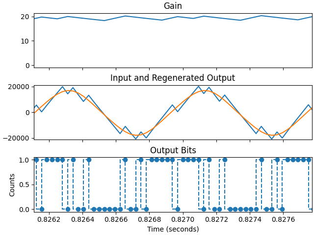
CVSD Encoder Input (Middle Orange), Feedback CVSD Decode (Blue), and Output CVSD Data (Bottom)
Our first attempt looks great according to the above plots, but when the CVSD data output was decoded by the decoder python script, the result was obviously distorted:
The output showed distortion that was not present when plotted by the encoder python script. After digging around in the code and comparing binary sequences from what was displayed in the encoder plots to the data actually written to file, I determine that the nibbles were getting swapped when writing ASCII hex encoded bytes to the output file. The output sounded great after changing the script to work one nibble at a time rather than one byte at a time.
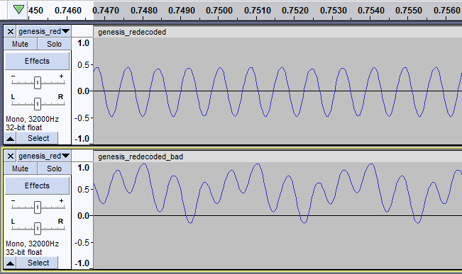
Comparison of Nibble Swapped Output to Correct Output
Data Resiliency
The above issue where audio was still intelligible with swapped nibbles is a good example of how resilient CVSD encoding is and how good humans are at audio signal processing. Just for fun, I wrote a script to flip bits in encoded CVSD to assess the impact of data corruption due to interference on the data lines. My general determination is that low error rates (1% or less) have less of an impact on CVSD encoded audio than they do on PCM encoded audio; in PCM if you have a bit flip on the most significant bit, there is an easily noticeable click on the output — in CVSD, a single errant bit will only move the output by the current gain value. However, it seems that at higher bit error rates — about 10% — PCM, though static-y, is more decipherable than PCM. I wrote scripts to corrupt both CVSD data and PCM data to compare the performance of both codes the results of which are shown below.