Capacitive Discharge Spot Welder
2018
I decided to build my own capacitive discharge (CD) spot welder after being frustrated by the low quality and high cost of commercial units. Anyone building battery packs using cylindrical lithium batteries should, with some exceptions, be using a capacitive discharge spot welder. Unlike normal spot welding, the duration of the weld pulse with CD welding is so short that the cell itself is not able to heat up much (which would run the risk of damaging it). Ultrasonic welding and laser welding are also options, but the cost and complexity of the required equipment is much higher than for CD welding. Soldering lithium batteries is not an acceptable option due to the risk of damage to the plastic separators inside the cells.Schematic
Layout
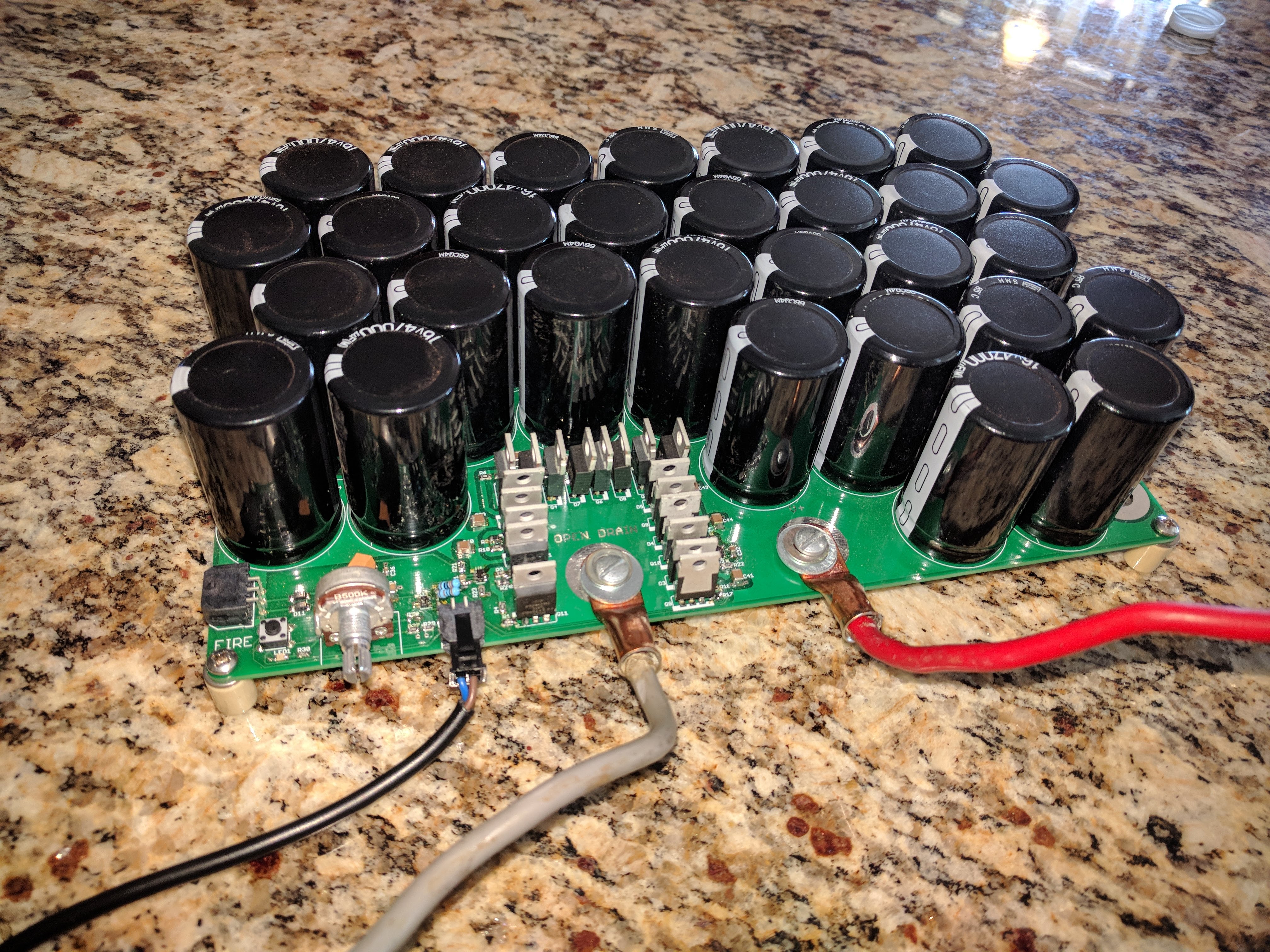
Front View of Spot Welder
Commercial CD spot welders are expensive. The cheapest model sold by Sunstone is in the $2-3k range, and I can say from experience that they are pretty not at all reliable. The eBay special units like the SUNKKO 709A aren’t even CD welders — they are normal spot welders with undersized transformers intended for low duty cycles. Hobbyist units vary widely in quality. From what I found, most either over-complicated the construction, were extremely inefficient, or abused some part of the setup during use. In my welder, everything is kept within the maximum ratings given by the manufacturer.
Requirements
Capacitors
Spot welders are typically rated in terms of Joules, but not all Joules are created equally in this context. Typically, the maximum joule rating is based on the energy stored in the capacitor bank and derived from E=1/2*C*V^2. The actual energy deposited into the spot weld itself and not into the capacitors, switches, and leads is much lower due to resistive losses. The fraction of the total resistance in the circuit that is from the actual weld joint determines the ‘efficiency’ of a welder.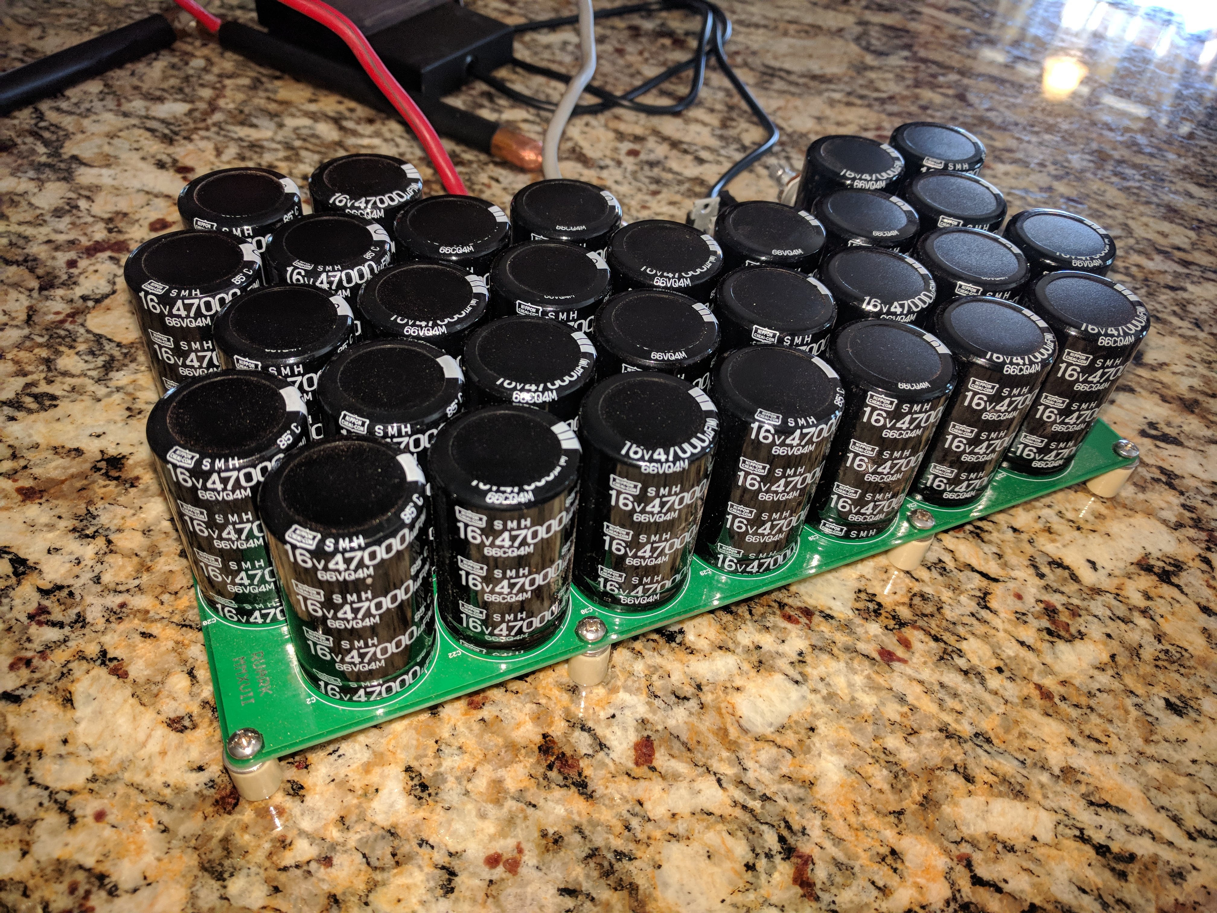
Back View of Spot Welder
For example, say you have an array of 6 2.7V 650F Maxwell super capacitors as this guy used. The internal resistance of each cell is 0.8 mOhm which adds up to 4.8mOhm. Allowing 1mOhm for switch and board resistance and another 1.5mOhm for lead resistance, the total parasitic resistance in the circuit is 7.1mOhm. If the weld itself has a resistance of 2mOhm, then only ~22% of the energy stored in the capacitors is transferred to the weld.
Another requirement is for the weld pulse to be short. Ideally, this will be on the order of 10ms to prevent heat from the weld conducting into the cell and increasing the size of the heat affected zone. The higher the internal resistance of the capacitors, the longer they take to discharge. With the capacitors I selected, the capacitors can dump 84J into the weld in 10 ms while the Maxwell supercap would take 14ms despite being much larger. The voltage of the capacitor bank also determines how quickly it is able to deliver power. A 16V 2F bank has the same energy as an 8V 8F bank, but the 8F bank will take (using the same switch, weld and lead resistance while setting cap resistance for the 1F bank to 0.5mOhm and to 0.125mOhm for 4F) four times as long to deliver 80J to the weld.
I ended up selecting the lowest farad / dollar standard aluminum electrolytic capacitor on digikey with a 16V rating: ESMH160VSN473MR50T. This is a 16V, 47mF, 14mOhm electrolytic capacitor. With 30 of them in parallel, the bank is 1.4F 0.46mOhm. The total cost of the bank is about $120. These capacitors were used in the second revision of the project which used super caps.
12-25V seems to be a reasonable operating range for these capacitor banks. Higher voltage caps have higher internal resistance which robs efficiency, and larger switches are needed to handle the current. This spot welder ended up being set up such that it used only about a third of the maximum stored energy per weld during its largest test to date.
Switches
There are three relevant ratings for switches in a CD welder:- Voltage Rating
- Maximum Current
- On Resistance
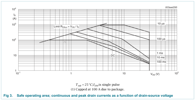
MOSFET Safe Operating Area
Since a pulse will last around 10ms, the maximum current with on resistance as a limiting factor is 350A. With a 0.46mOhm capacitor bank at 16V, 0.21 mOhm (ten 2.1mOhm in parallel) switch, and 1.5mOhm leads into a 1mOhm weld, the maximum current should be 5kA. This is a decaying exponential, though, so the RMS current over a 10ms pulse is only 2.25kA which means that the systems is in the safe operating area. If the system were to be discharged into a true dead short, it is possible that damage would occur since the RMS current during the first 1ms would be 6.3kA which exceeds the 500A per device limit from the datasheet. Should any devices ever blow out, I plan to replace them all with a device that can handle twice the current (at twice the price).
Gate Drivers
The faster the rise time of the gate drive waveform, the lower the loss due to switching in the transistors will be. For this reason, I used two separate gate drivers each running five MOSFETs. I was a bit hastey in selecting a gate driver, so I ended up with one that acts more like a voltage buffer than a normal gate driver. Whatever voltage is applied to the input of the driver will be applied to the gate, so while it can source and sink up to 5A with fast rise and fall times, it does not apply the full 10-15V to the gates that I would prefer. Fortunately, these are logic level FETs and work fine with a 5V gate drive. The second revision of this board will probably use a more typical gate driver like this one.Each FET has its own gate drive resistor and chip ferrite to prevent unwanted oscillations between the gate capacitances. The gate drive traces are wide and over unbroken ground plane to reduce parasitic inductance.
Control
I elected to go with a simple single pulse controller for this welder based on my experience doing thousands of welds using a commercial spot welder. I could never notice the difference between dual and single pulse mode, so I only bothered to implement single pulse on this prototype. I could have used a dual comparator circuit, but I had an LTC6993 single shot pulse generator in a promotional package I wanted to try out because it is a neat little part. It uses a voltage divider to set the range of pulse width and a potentiometer input to fine tune the width over that range. This chip is susceptible to causing double fires due to switch bounce, so an additional circuit to mitigate that should be added to a second revision of this board. I added a four pin Molex uFit connector so that an external footswitch could be used.The control circuitry and gate driver are powered by a local supply separated from the capacitor bank by diodes. If the capacitor bank fully discharges during a pulse, the control circuitry will remain powered until after the pulse has ended to prevent the FETs from being driven in the linear region as the supply reaches zero. Construction
I wanted this to be a simple board that required no external hardware beyond standoffs, the probes, and a foot switch. I ordered the board through EasyEDA and had it made in two ounce copper. I got five boards and paid less than $40 total despite this being the largest board by area that I have had manufactured to date. There are no bussbars or multiple boards that have to be connected together, its just one large board that gets the job done.
Power
I wanted the board to run off of a standard current limited bench supply, so I made the input a simple banana jack connection. Power input is also broken out on one of the Molex Operation and ResultsI initially tested the board by pushing current though low resistance wire and monitoring the current. From there I worked up the current until I reached spot welding current levels. Next, I manufactured probes from copper rod. They ended up being a but large at 0.5″ in diameter, but I should be able to make them serviceable by turning the ends down a bit on a lathe. With these probes, I was able to make clean welds using nickel tabbing wire using only a half of the maximum energy available.

Oversized Probes
I brought the welder with me when I went to visit some friends in Rolla which is where I went for undergrad. When I showed up at the Student Design Center, members of the Mars Rover Team were sitting in front of a Sunstone spot welder frustrated that it had yet again decided to stop working without presenting any error messages. I pulled by welder out of may car, they hooked the Sunstone’s probes (the best part of the product) to by welder, and they proceeded to weld the rest of their battery pack. They probably did 500 welds over the next hour, and the welder worked great aside from some issues with the incredibly cheap foot switch I bought for it. I ended up replacing the switch inside the footswitch with one I picked up at a surplus store in Albuquerque, and that fixed the double triggering issue.

Spot Welder In Use
After all of these welds, the capacitors did not heat up perceptibly, and the switches had only heated up by 10 C above ambient: 91F.
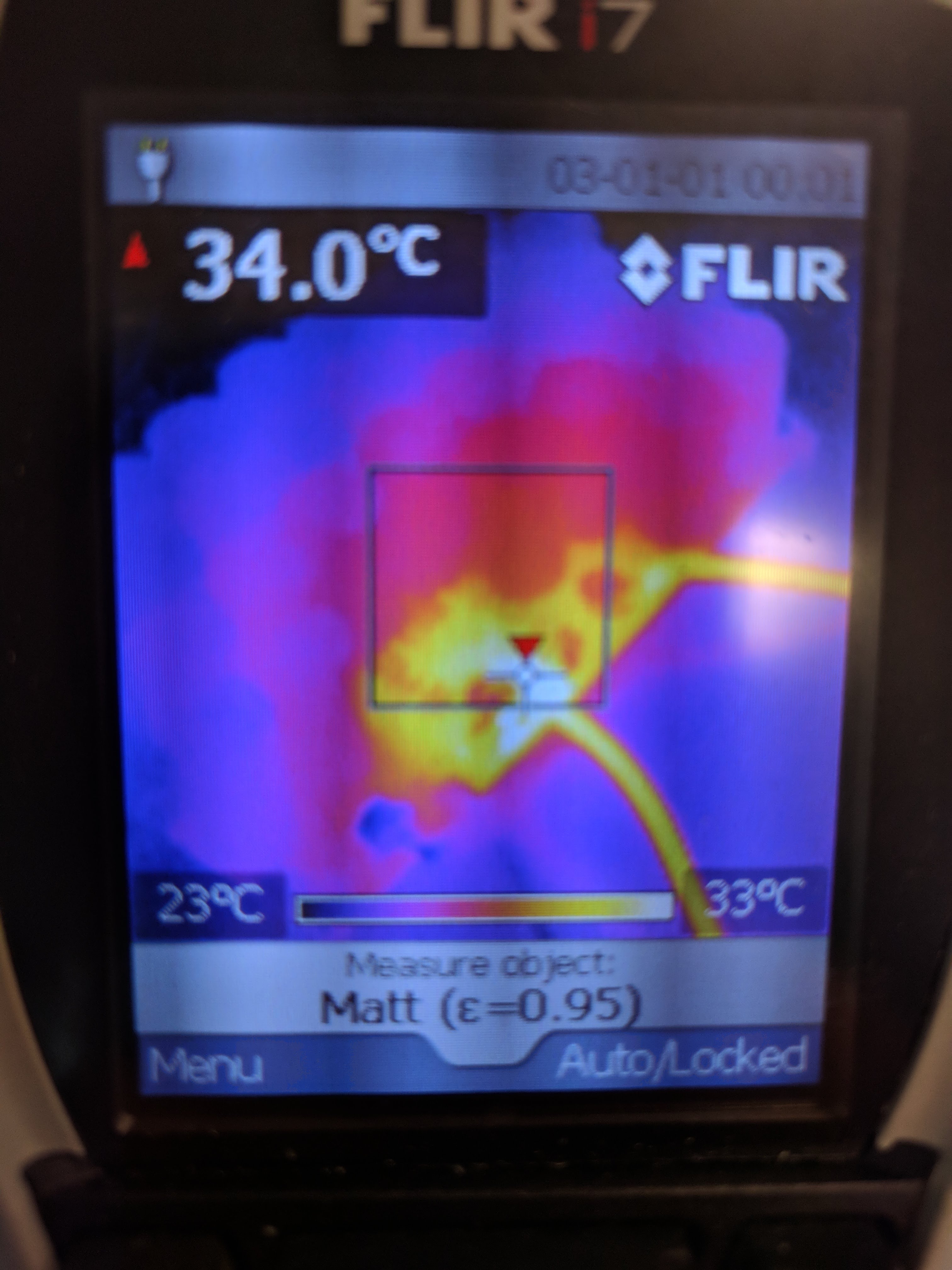
Spot Welder After Hundreds of Welds on FLIR Camera
Update 11/6/2022
At first the snap in capacitors I used worked just fine without soldering them in place. I initially didn’t solder them so that they wouldn’t be wasted if there was a problem with the board that required a respin, but it turned out that the joints around the capacitor legs are firm enough just from friction that the welder can be used normally without the joints being soldered. They worked fine as recently as last year, but this time when I pulled this out for a friend to use to rebuild an 18650 pack it didn't work. I noticed lots of popping when the capacitors were moved, and I realized the leads were no longer making good contact -- probably due to the HASL finish finally oxidizing enough for it to be a problem. After soldering the capacitors in, I was back to full power.