DNVT Encoding and Control Codewords
2023
DNVTs (Digital Non-secure Voice Terminals) communicate in full duplex at either 16kbps or 32kbps using separate transmit and receive differential pairs. Data on these differential pairs is encoded with Differential Manchester Encoding. This has two benefits: the data lines can be transformer coupled because Manchester encoded data has no DC component, and the polarity of the data lines is irrelevant because Differential Manchester encodes data not by the absolute symbol, but by transitions between symbols as described below.
DNVT States As Implemented by Custom Switch
The bitstream on the line is unframed — there is no concept of definite starts and stops for particular bytes. This is fine for the CVSD encoded audio, but it presents a challenge for sending control messages to the phones. The solution is that control data is sent in-band with cyclically permutable codewords. In order to get these phones working, I had to figure out that these codewords were as well as what function they performed. The IEEE Paper includes a table of codeword types, but not the bit sequences that they correspond to. This page covers the results of the reverse engineering performed here as well as the theory behind the encoding.
Differential Manchester Encoding
Differential Manchester encoding, like Manchester encoding, has two symbols: a low to high transition and a high to low transition. Each symbol consists of two half periods. If the data rate is 1 kbps, the period of each symbol is 1ms and the period of each half period is 0.5 ms. A low-to-high symbol is, therefore, low for 0.5 ms and then high for 0.5 ms and the opposite is true for high-to-low symbols. While Manchester encoding maps binary 0 and 1 to high-to-low and low-to-high symbols, Differential Manchester encoding maps binary one to a change in transmitted symbol and binary 0 to a repetition of the previous symbol.

Example of Differential Manchester Encoding from "Introduction to Communications Systems" by Stremler, 1982
Another way of thinking about differential Manchester encoding is as a phase modulator with a square wave output which will inverts its phase by 180 degrees every symbol if the data to be encoded is 1 and will maintain its phase if the data to be encoded is 0. As a result, you can decode Differential Manchester with a simple algorithm which looks for 'long' and 'short' states. When binary 1 is encoded, the signal will remain either high or low (depending on its previous state) for two half-periods (long). An encoded zero, however, will always appear as two consecutive short periods of alternate states. This can be seen in the diagram above. This comes from a book on communications theory that I picked up after an engineer retired at Sandia National Laboratories while I was there as an intern. It is from 1982, so it could have conceivably been used as a reference by engineers working on the design of DNVTs.
Beyond the benefits already mentioned, Differential Manchester also has the benefit of allowing for each clock recovery. If you encode all ones, the signal on the line will be a square wave with a frequency equal to the data date. If you encode all zeros, the signal on the line will be a square wave with a frequency twice that of the data rate. Simply comparing long and short intervals works great for post-processing on machines with plenty of memory, but you can use a PLL to recover a clock signal that you can use to, in real time, sample the received data. For my initial testing and to validate the algorithm I implemented on an STM32, I wrote a python script that parses CSV files from oscilloscope captures of Manchester encoded data. It is slow, but it does work.
If you know the data rate in advance, you can also decode the data by triggering off changes in state, inhibiting re-triggering for 3/4 the symbol period, and then sampling the line. If the state transition you triggered on was high to low and the signal is high when sampled after 3/4 of a symbol period, then you know that there was a transition and that the data encoded was zero. If the signal were low when you sampled it, you would know that there was no transition in between your trigger and sampling meaning that the data encoded was one. The opposite is try when you trigger on low to high transitions. You do need to trigger on both low to high and high to low transitions for this method to work. This is the method used by the Raspberry Pi Pico.

Raspberry Pi RP2040 Datasheet Examples
We are using the PIO (Programmable Input Output) blocks of a Raspberry Pi Pico for this encoding end decoding since these blocks are specifically designed to handle arbitrary digital formats like this. The datasheet for the RP2040 actually includes a reference implementation of differential Manchester encoding and decoding in section 3.6.6. Note that the assignment of 1 and 0 in Differential Manchester to whether the phase inverts or remains the same is arbitrary; my text book reference defines the absence of a phase change as 0 and the presence of a phase change (leading to a 'long' period) as 1. The Raspberry Pi Pico default implementation uses the opposite nomenclature which lead to some early confusion. Reversing the meaning of 1 and 0 with the DNVTs just means that my concept of control codes is inverted and that the audio waveform is inverted which has no practical consequence for normal operation of the phones.
Cyclically Permutable Codewords
As mentioned earlier, the data transmitted and received by DNVTs is not framed. There is no concept of beginning and ends for bytes. The data is a continuous bitstream. The codewords are eight bits long and are sent continuously until acknowledged by the phone or switch (or if either times out). In order to tell these codewords apart, they need to be unique regardless of which eight bit sequence in the stream that you look at. For example, 0b0000 0001 can't be distinguished from 0b1000 0000 because you can generate one from the other by bit shifting. Put another way, 0b0000 0001 and 0b1000 0000 are cyclic permutation of the same codeword. 0b0000 0001 is distinguishable from 0b000 0011 because you can't generate one from the other by bit shifting, so they are permutations of different codewords.
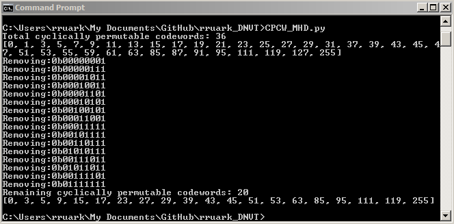
Cyclically Permutable Codewords as Determined by Python Script
The IEEE paper which describes the operation of DNVTs states that of the 256 possible eight bit sequences, only 20 are used as codewords. To find them, I wrote a simple python script that brute force checks all codewords. This yielded 36 codewords. I had a hunch that if only 20 of these were used, it would be the ones with the greatest Hamming distance to other codewords, and I confirmed that hunch with a another quick script that goes through the list of valid codewords and eliminates the next codeword in the list if it is hamming distance 1 from the previous codeword. The script determined that 16 of the 36 codewords are Hamming distance one to another codeword. If the Hamming distance between two codewords is one, a single bit error could result in one codeword being interpreted as a different codeword. By marking the 16 codewords with Hamming distance one as invalid, the remaining 20 codewords of Hamming distance two or greater require two bit errors for any codeword to be interpreted as any other valid codeword. The practical benefit of this is that bit errors from noisy lines are less likely to impact the operation of the phones.
I think it makes the most sense to refer to these codewords by their minimum value. 0b0000 0001 and 0b1000 0000 are cyclic permutation of the same codeword, and I think it makes more sense to call this codeword 0d001 instead of 0d128. I'll refer to the minimum value form as the normalized form:
Codewords in Order:
| Decimal Value | Hex Value | Binary Value |
|---|---|---|
| 0 | 0x00 | 0000 0000 |
| 3 | 0x03 | 0000 0011 |
| 5 | 0x05 | 0000 0101 |
| 9 | 0x09 | 0000 1001 |
| 15 | 0x0F | 0000 1111 |
| 17 | 0x11 | 0001 0001 |
| 23 | 0x17 | 0001 0111 |
| 27 | 0x1B | 0001 1011 |
| 29 | 0x1D | 0001 1101 |
| 39 | 0x27 | 0010 0111 |
| 43 | 0x2B | 0010 1011 |
| 45 | 0x2D | 0010 1101 |
| 51 | 0x33 | 0011 0011 |
| 53 | 0x35 | 0011 0101 |
| 63 | 0x3F | 0011 1111 |
| 85 | 0x55 | 0101 0101 |
| 95 | 0x5F | 0101 1111 |
| 111 | 0x6F | 0110 1111 |
| 119 | 0x77 | 0111 0111 |
| 255 | 0xFF | 1111 1111 |
Codeword Assignment
To map these codewords to specific functions, I used brute force: Knowing the expected states from the IEEE paper, I went through all 20 codewords in each state until I found the codeword needed to get the phone into the next state. I did this with some crappy timer driven code on an STM32F103 programmed using the Arduino IDE that I will describe in the next page on the initial test boards. There is a specification for these codewords, TT-A3-90l5-0046, but that document is not publicly available.
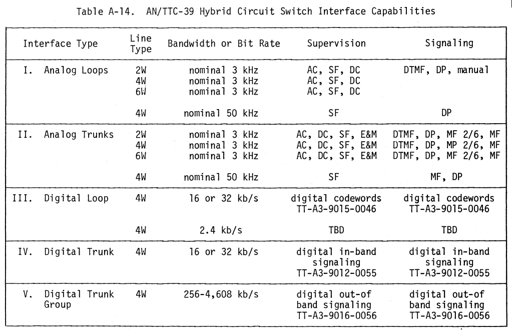
Table from NTIA Report 83-123 Showing Codeword Specification for DNVTs
The term 'codeword' here is overloaded. It refers both to the binary sequence sent over the line as well as the function (RING, SEIZE, etc.) Some codeword sequences are used for different functions depending on the state of the phone. The switch also re-uses codeword sequences for different purposes. Here is the mapping of codeword functions to codeword sequences:
| Function | From Switch | From DNVT | Codeword (0d) | Codeword (0x) | Codeword (0b) |
|---|---|---|---|---|---|
| FORCE CLEAR | X | Unsure | |||
| IDLE | X | Unsure | |||
| CUE | X | 63 | 3F | 0011 1111 | |
| SEIZE | X | 111 | 6F | 0110 1111 | |
| DIAL | X | 53 | 35 | 0011 0101 | |
| INTERDIGIT | X | 85 | 55 | 0101 0101 | |
| GO TO PLAIN TEXT | X | 3 | 03 | 000 0011 | |
| LOCK IN | X | 0 | 00 | 0000 0000 | |
| LOCK IN ACK | X | 0 | 00 | 0000 0000 | |
| RELEASE | X | 95 | 5F | 0101 1111 | |
| RELEASE ACK | X | 43 | 2B | 0010 1011 | |
| RING VOICE | X | 45 | 2D | 0010 1101 | |
| RING ACK | X | 53 | 35 | 0011 0101 | |
| RING TRIP | X | 43 | 2B | 0010 1011 | |
| Digit 0 | X | 5 | 05 | 0000 0101 | |
| Digit 1 | X | 15 | 0F | 0000 1111 | |
| Digit 2 | X | 39 | 27 | 0001 1011 | |
| Digit 3 | X | 63 | 3F | 0011 1111 | |
| Digit 4 | X | 29 | 1D | 0001 1101 | |
| Digit 5 | X | 3 | 03 | 0000 0011 | |
| Digit 6 | X | 43 | 2B | 0010 1011 | |
| Digit 7 | X | 119 | 77 | 0111 0111 | |
| Digit 8 | X | 27 | 1B | 0001 1011 | |
| Digit 9 | X | 9 | 09 | 0000 1001 | |
| R | X | 111 | 6F | 0110 1111 | |
| C (Conference Request) | X | 17 | 11 | 0001 0001 | |
| P (Priority) | X | 23 | 17 | 0001 0111 | |
| I (Immediate) | X | 45 | 2D | 0010 1101 | |
| F (Flash) | X | 51 | 33 | 0011 0011 | |
| FO (Flash Override) | X | 53 | 35 | 0011 0101 | |
| RATE CHANGE | X | Unsure | |||
| RATE CHANGE ACK | X | Unsure | |||
| RECALL | X | Unsure |
Note that I have found at least one use for every codeword aside from all ones (255).
State Diagram
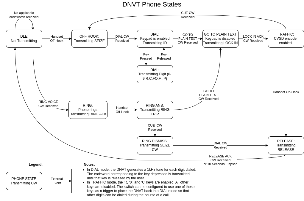
To map these codewords to specific functions, I used brute force as described here. The term 'codeword' here is overloaded. It refers both to the binary sequence sent over the line as well as the function (RING, SEIZE, etc.) Some Codewords share the same binary sequence because they are applicable to different states. For example, the RING ACK and FLASH OVERRIDE are both encoded by the phone as 0x35.
DNVT States As Implemented by Custom Switch
I found a few situations that did not align with the state diagram in the IEEE paper, and I could not figure out what bit sequences corresponded to IDLE, FORCE CLEAR, and RECALL. The RECALL codeword could possible be the same as the R codeword since I don't know under what circumstances the phone could send an "Emergency Access" code (as defined in the DNVT manual). In order to get a ringing phone to stop ringing without taking it off hook, had to send the phone CUE, followed by DIAL and then RELEASE ACK. In this context, the binary sequence corresponding to DIAL may refer to IDLE or FORCE CLEAR. Either way, the RING DISMISS state shown in my state diagram does not have a corresponding state on the phase diagram below.
DNVT States Transitions from IEEE Paper
I could not find a single codeword that would transition the phone from RING directly to RELEASE as the phase diagram indicates that I should be able to do, but I am still able to force the phones into all of the states required for normal operation. The only thing that would be nice to add is support for changing phones from 32 kbps to 16 kbps on the fly with the RATE CHANGE and RATE CHANGE ACK codewords. As it is right now, the switch has no way of operating some phones at 16 kbps and others at 32 kbps — all must be at one or the other. TA-1035 only supports 16 kbps as far as I can tell, so if you want to attach any of these phones to a switch, you must set all the phones to 16 kbps. The reason not to just default everything to 16 kbps is that audio quality is better at 32 kbps.