How USB Lighters Work
2018
LTSPICE SimulationUSB lighters, like the one below, work by driving a flyback transformer using an 1860 lithium ion battery as a power source. The Flyback is driven by a single low side N-Channel MOSFET which is driven by a micro controller (no gate driver). The drain voltage of the MOSFET is clamped by avalanche in the MOSFET itself -- there is no external snubber. There is always voltage across the MOSFET when the circuit is not active -- the control button only controls power to the micro controller. If the MOSFET were to fail short, the battery would be shorted out.

Typical USB Lighter
I had a roommate in Ann Arbor that had one of these USB lighters. After seeing that they were only $15 on Amazon (and seeing how much fun they were) I bought one for myself. The only flaw in the product is the god-aweful high pitched noise it makes, so I took it apart as soon as it arrived to see if I could eliminate that. I was also curious what innovaton allowed this product to exist now and not ten years ago. My best guess is a combination of low cost lithium ion batteries and low cost logic level power MOSFETs with decent avalanche characteristics. The rest of the circuit is pretty straightforward. The flyback transformer itself is totally potted.
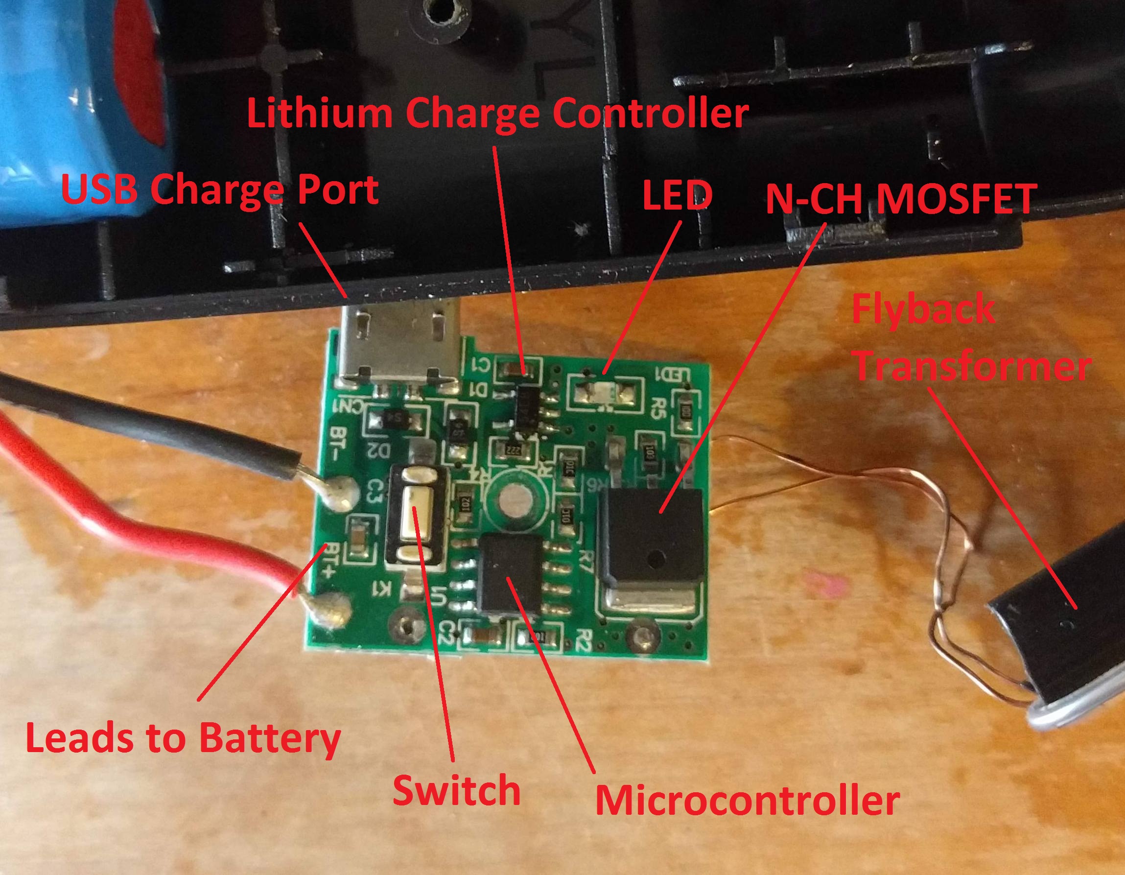
Overview of Driver Board
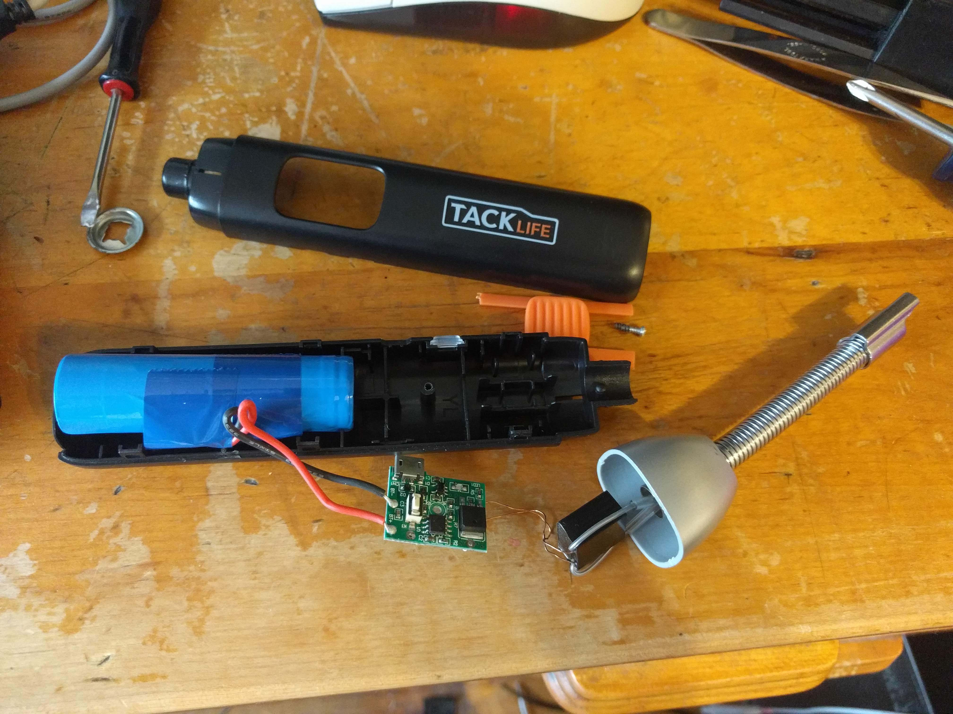
Full Assembly
The source of the noise was the fact that the device switched in the audible range. The unit I measured was around 16kHz. Above 10kHz, you run into the problem of older engineers not being able to hear switching noise and not realizing it is an issue. I haven't had the chance to do this yet, but I plan to replace the micro controller with something that is pin compatible so that I can bring the switching frequency up to 20KHz. I'll also increase the duty cycle to maintain the same peak current as I currently see to get a bit more power out of the unit.
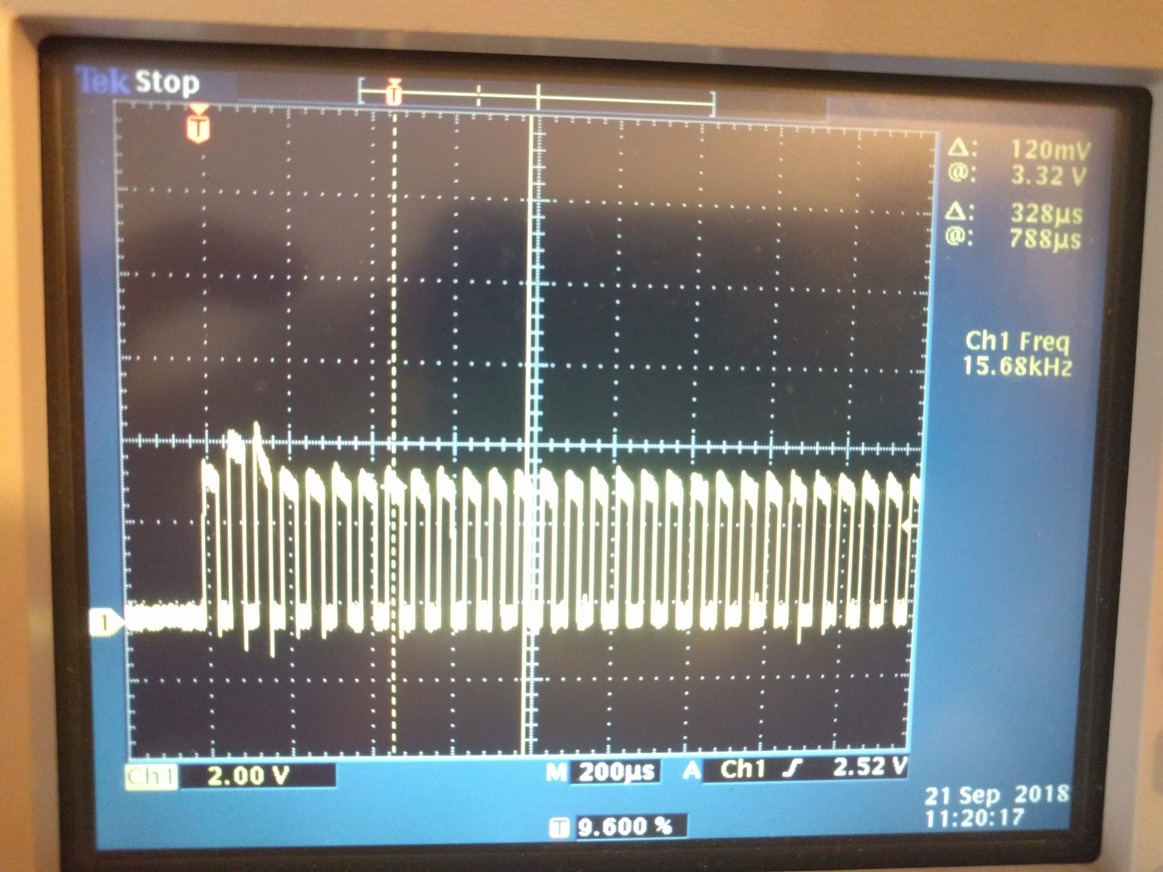
MOSFET Gate to Source Voltage After Switch Pressed

MOSFET Drain to Source Voltage
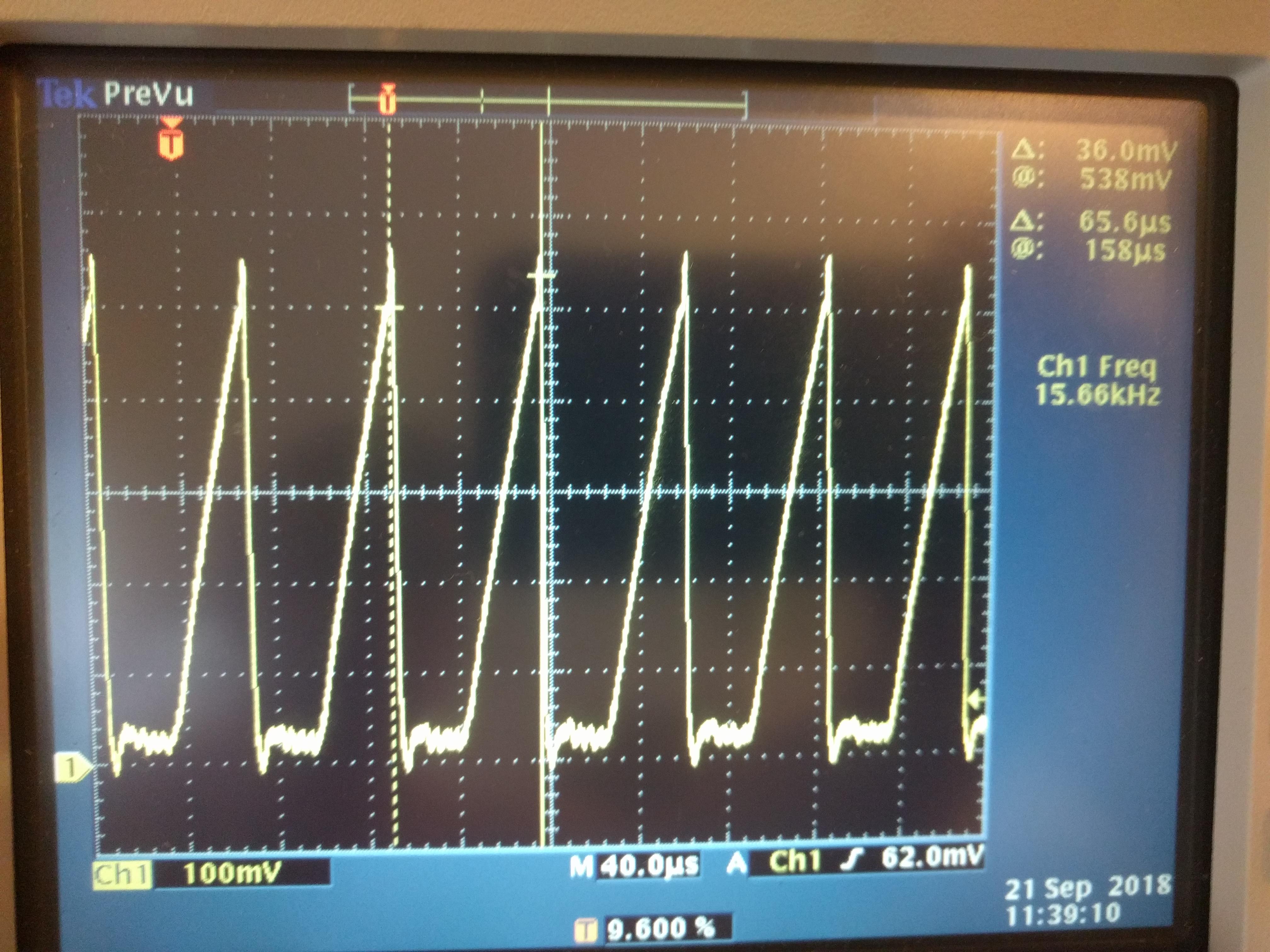
Input Current From Battery
LTSPICE Simulation
The inductance of the primary of the flyback transformer can be calculated from the slope of the current waveform. It turned out to be around 22uH. The inductance of the secondary can be calculated as well, but other measurements would be required, so I put a guess that results in an open circuit voltage on the output of 20kV in my simulation. I selected a MOSFET with a suitably low turn on voltage, but since LTSPICE doesn't model avalanche on MOSFETs, I had to throw a Zener diode in parallel to get the correct clamping on the switched node.
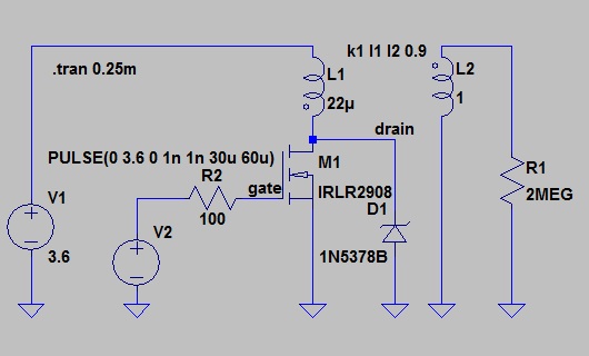
LTSPICE Schematic
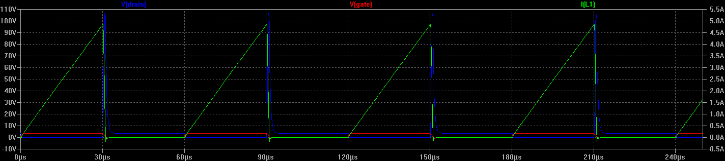
Simulated Waveforms