VFD Tube Clock
2018
Old display technology is neat. Be it Nixie Tubes, Vacuum Florescent, split-flap or something more arcane, someone has probably built a clock using it. I personally like VFD displays for their crispness, longevity and reliability. When I found that you could buy new old stock (NOS) single digit Russian tubes (IV-6) from the early 1980’s for $2 each, I decided to build a clock of my own.
SchematicLayout
EagleCAD Files
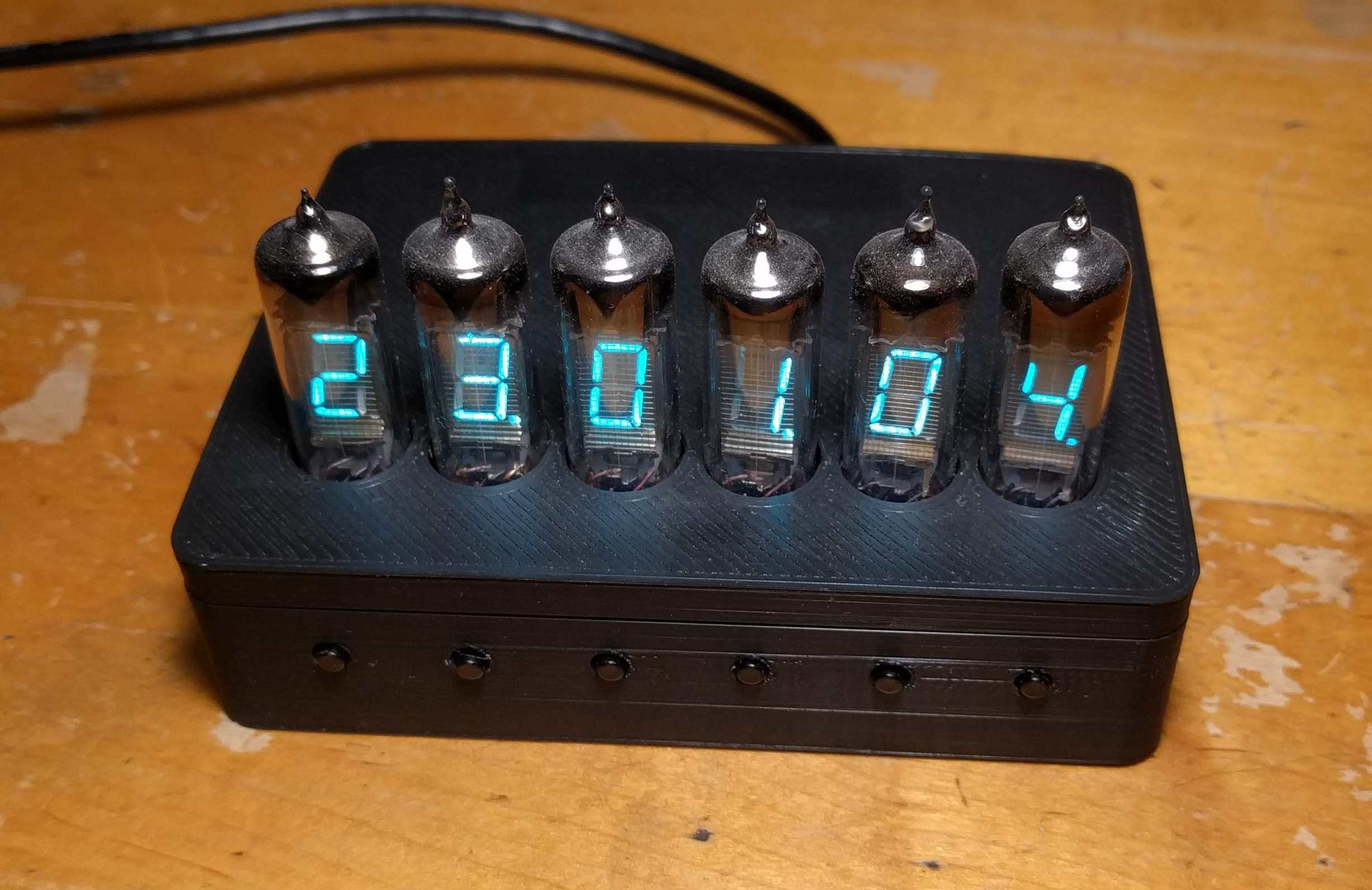
Assembled Clock
Timekeeping
The clock uses a DS3231 I2C RTC to keep accurate time. The board has a CR2032 backup cell on so it continues to keep time without displaying it even when power is removed. The RTC is accurate to +/- 2 PPM over normal temperatures, so at worst it should only drift by a minute per year. I haven’t done any long term testing yet, but over the 14 days that it has been running so far, the seconds still tick exactly with time.is.
Its worth noting that prototyping boards with these chips on them can be purchased on Ebay for less than the cost per unit in quantities of 1,000 of just the chip on Digikey. That suggests that the chips on these prototyping boards is counterfeit, that they didn’t pass final QC, or that they were made on a ‘ghost’ shift. Some people have had success with them, but its not worth my time to desolder a sketchy part off of a Chinese board to save $4. The ‘cheap’ versions of this part do at least seem to be more reliable than counterfeit FT232RLs which is a part that I am also using on this board.
I also included a serial header with the first four pins of the standard GPS prototyping board header so that a GPS unit can be added in the future for even more accurate timekeeping.
Power
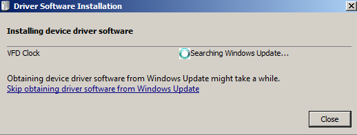
I designed the clock to pull all of its power from a single 5V USB input. The microcontroller and all of the ICs on the board run directly off of the 5V input. The finished board pulls a bit less than 500mA from the USB line, which is a power level that virtually every USB wall adapter and the majority of computers can support. FTDI provides a configuration utility that can be used to program a few bits of information into the FT232RL. Here I am using it to communicate to the computer how much power the device is supposed to draw as well as to set the name and manufacturer of the board.
Two other voltages are required by the VFD tubes to function: Filament and Plate.
Filament
The filament voltage heats the filament to just slightly red hot so that it can act as a source of electrons through thermionic emission. The IV-6 tubes require 50mA each at around 1.2V to keep the filament hot enough. If I were to use a linear regulator powered off of the 5V input to drive the filaments, the board would pull 300mA from that alone. Instead, I included a buck converter to step the input 5V down to 1.2V. Assuming 72% efficiency, the buck converter should only pull ~100mA.
That efficiency is as low as it because the buck converter is not synchronously rectified. 0.6V of the output voltage is lost in the diode inside the converter, so a rough estimate of efficiency — not including switching and conduction losses in the pass MOSFET inside the converter — is Vout/(Vout+0.6V*(1-D)) where D is the duty cycle of roughly Vout/Vin=0.24 . This still beats the efficiency of a linear regulator in this application: Vout/Vin= 1.2/5 = 24%
Plate
In order for these tubes to light up, at least 12V (25V is the datasheet suggested value) needs to be present between each segment (the plate) and the filament. I used a boost converter to generate this voltage from the input 5V. I included a potentiometer to adjust the output voltage as well so that the tubes could be dimmed. I used a 10 turn potentiometer here, but I really should have used a single turn potentiometer simply because having that level of precision is unnecessary.
I always limit the bounds of potentiometers in feedback circuits be adding extra outside components. I have had to deal with several circuits made by inexperienced designers that would destroy themselves if the potentiometer is set to the wrong position. Feedback circuits associated with boost converters require careful attention because if the potentiometer becomes an open circuit the controller will try to create an output voltage beyond the ratings of its switch and diodes.
Paralleling the potentiometer with another resistor and adding a series resistor to it accomplishes the goal of limiting the range of output voltages that can be set by it.
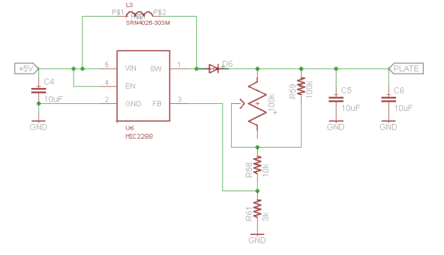
Boost Converter Circuit
VFD Driver
Since VFD driver chips are a specialty part, I decided to make the VFD driver from scratch.This circuit consists of I2C IO expanders which give the microcontroller 48 individually controllable outputs and 48 level shifters to take the outputs of the IO Expanders and boost them to plate voltage.
There are a lot of different ways of building level shifters, and I came up an application specific one that minimized part count. Since a small amount of leakage into the segments that are off is unnoticeable, I as able to get rid of the pull up resistor on the base of the PNP. Since it doesn’t matter if the output floats at some level higher than the threshold voltage for seeing light, I did away with the output pull down resistor as well. While I had expected the voltage of the segments that are off to float (which is why I added a Zener to the simulation to approximate the threshold voltage) it actually turns out that the segments go all the way to 0.0V when they are turned off.
I also combined the PNP base drive and NPN base drive resistor into one resistor on the emitter of the NPN. The output of the I2C IO expander is connected directly to the base of the NPN. The logic level of the input can be anything from the threshold voltage of the transistor up to the plate voltage. Its a bit unconventional, but its reliable and works just fine.
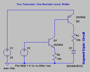
Level Shifter Schematic
This is not how these tubes are normally driven. These tubes, like typical triodes, have a grid connection. In a typical triode, this would be used like the gate on a MOSFET to control the flow of current between the plate and the cathode. For VFDs, the grid is used as a binary input which can very quickly control whether current is able to flow in the tube. This is used to multiplex the tubes so that the segments of each tube can be paralleled with the corresponding segments in each other tube thereby reducing the number of outputs required from the control circuit from 48 to 14 (8 segments + 6 grids).
The idea behind the multiplexing here is that if you toggle between the tubes quickly enough it will appear that the tubes are all lit simultaneously. To compensate for the fact that each digit is only on for 1/6 of the time, a higher plate voltage (50V) is used. This is the way that these displays are almost always implemented, but I hate flicker and I was not sure that I could get the 328P to toggle between segments quickly enough for flicker to not be noticeable. I also like that the board will hold its display indefinitely even if the microcontroller is put in reset. The time doesn’t update, but it doesn’t do anything bad like run a single tube at 50V constantly while the microcontroller is booting up.
Since I am not using the grid for its intended purpose, I tied it high to always allow current to flow in the tubes.
Control
The whole board is controlled by a DIP packaged APMEGA 328P microcontroller running the Arduino. I could have used a surface mount package, but I like the ability to swap chips if necessary, and the DIP package was still shorter than the buttons on the front anyway.
The microcontroller reads the time from the RTC over I2C and then sets the IO expanders over I2C. The microcontroller is programmed over the USB interface through a FT232RL USB to serial converter chip using the standard Arduino IDE.
User Interface
The board has six input buttons on the front lined up with the six display tubes. The board also has 1206 package green LEDs placed in front of each tube that can be turned on and off all at the same time as well as a buzzer. The buzzer and lights could be used for an alarm functionality.
The initial time is programmed through the serial interface, and after that the front buttons can be used to change the time. The buttons are wired to GPIO on the 328P, so they can be programmed to do whatever is needed. For the time being, the buttons only allow the time to be adjusted. The leftmost two increment and decrement hours, the middle two increment and decrement minutes, and the right two increment and hold seconds. The hold functionality is so that the time can be set to a point a few seconds in the future and then manually held at that time until it is accurate. This lets the board have better than 1 second configuration granularity.
Enclosure
I had originally intended to put this in a black painted aluminum project box, but I decided that it would look better if I 3D printed a more shallow enclosure. The tubes and buttons stick out of the top of the enclosure. In addition to being smaller, the plastic enclosure allows RF through which is important if I add a GPS receiver.
Other Pictures
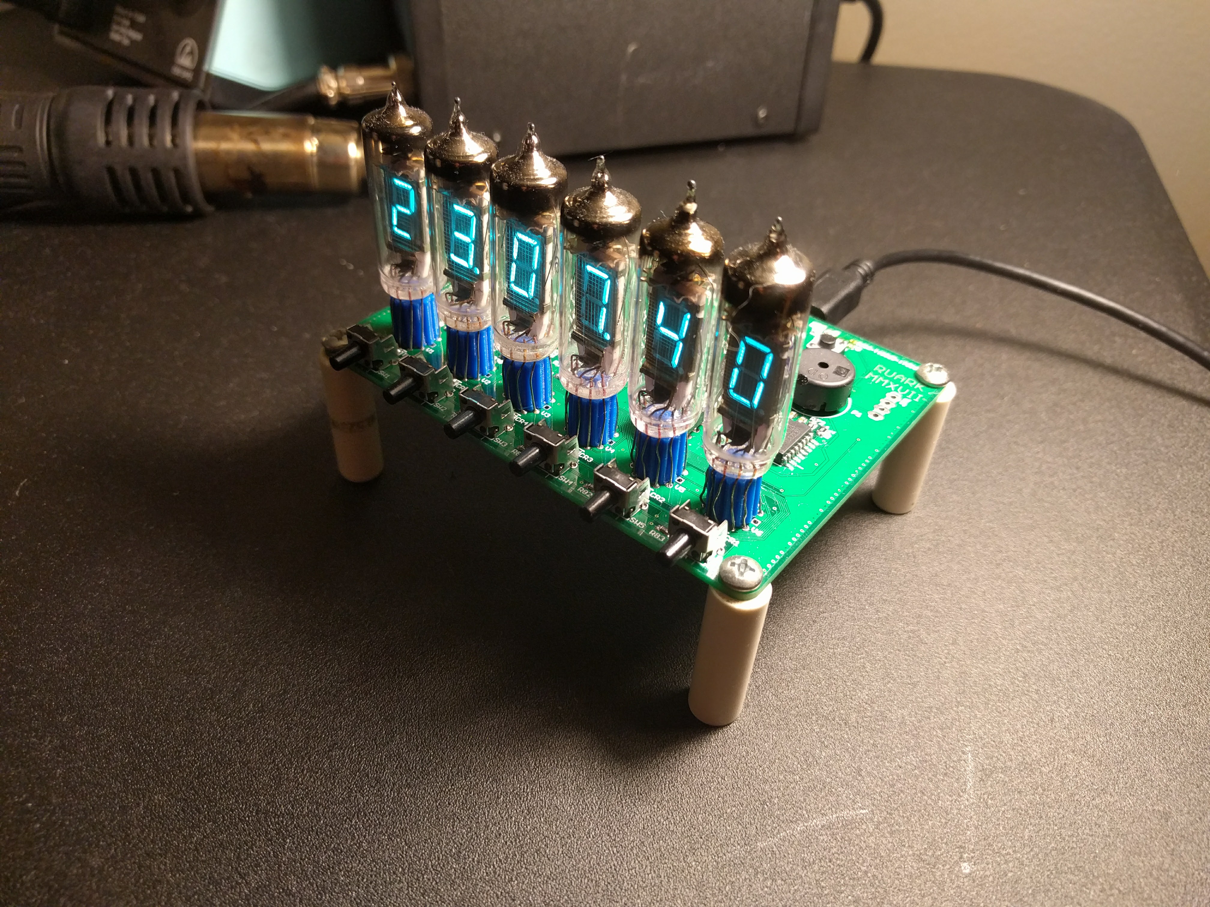
Clock Outside of its Case
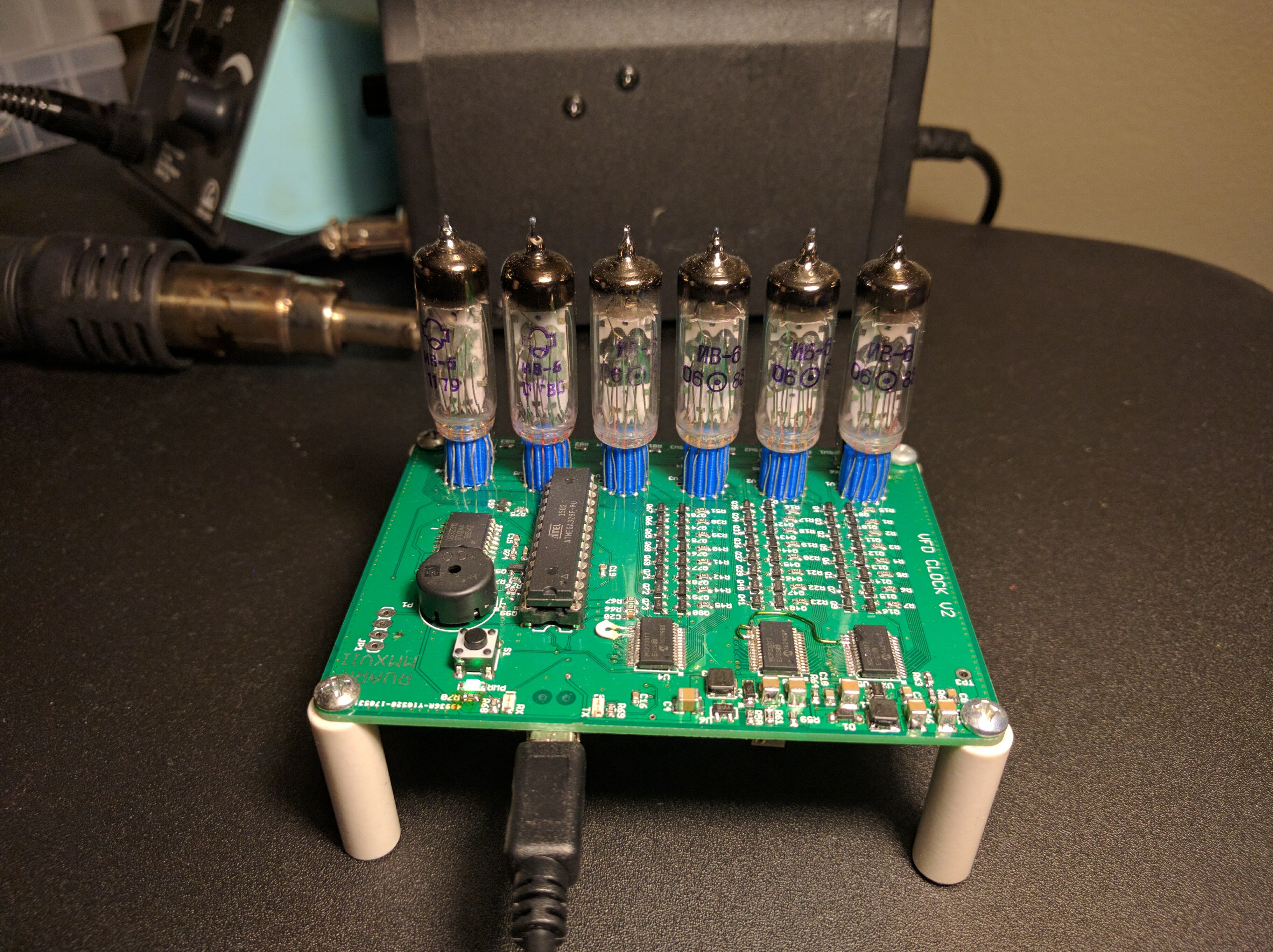
Back View
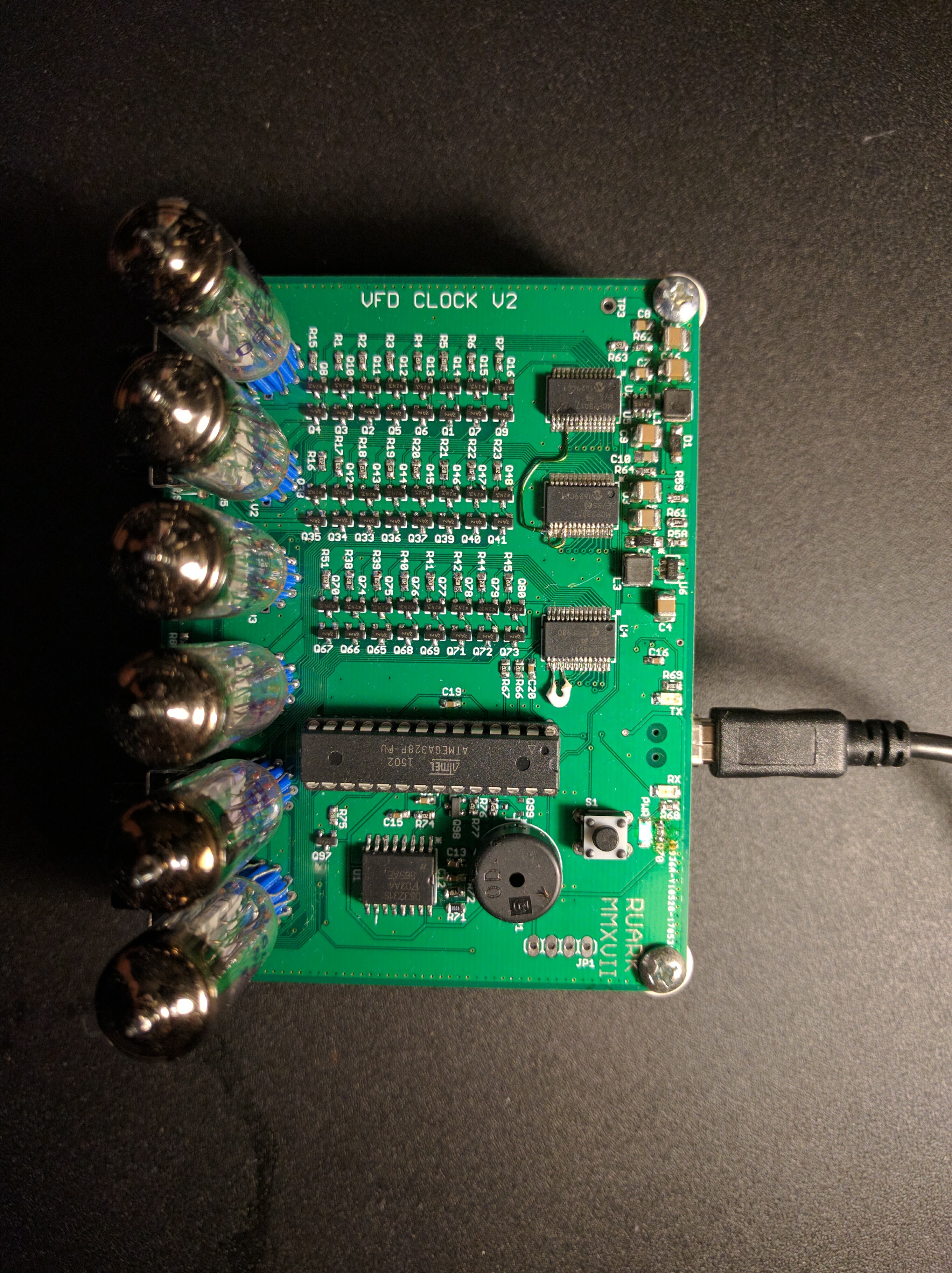
Top View
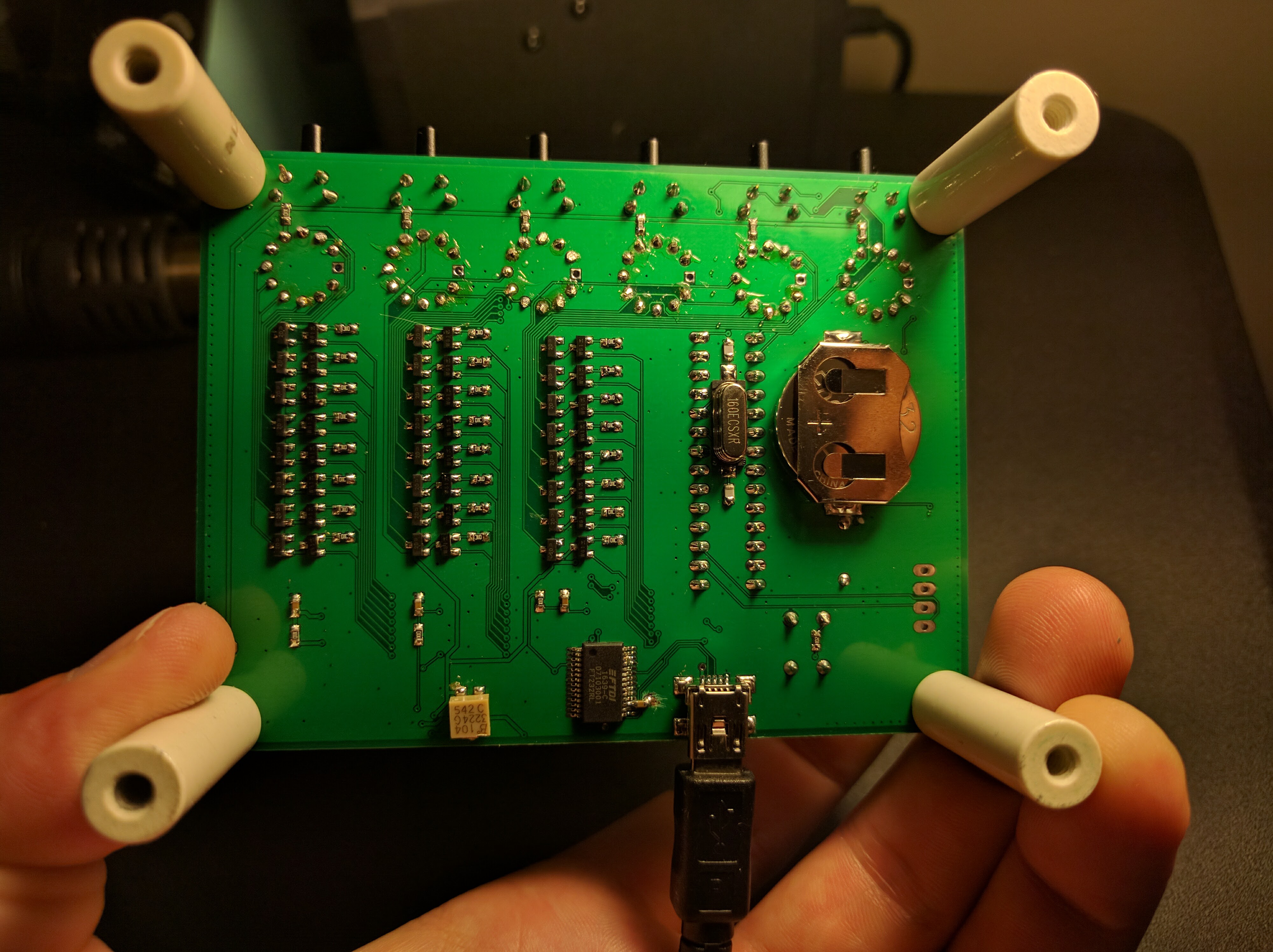
Bottom View