PCB Trace Fuses
2020
PCB trace fuses are a tempting alternative to adding actual fuses to a design. I started wondering about them when I designed my Leaf Battery power bank. I wanted to protect the battery sense leads from accidental mechanical shorts and was annoyed by the high price of surface mount fuses. When you look for information on how to design PCB trace fuses, however, very little comes up. There is a simulation-only white paper by Brooks and Adam and a number of Stack Exchange posts, but I could find no actual test data on PCB trace fuses. With PCBs from China being as cheap as they are, I decided to make a board with an array of trace fuses that fit between the pads of a 1206 footprint and measure the characteristics of these fuses for myself.
EagleCAD FilesFindings
- Trace fuses are not well suited for protecting against sustained moderate over-current events as the fuse can char the PCB resulting in a literal fire.
- Trace fuses work reasonably well at protecting against large overcurrent events such as reverse connected batteries and actual short circuits.
- Meandered trace fuses provide a more consistent time to blow, but they can also cause increased local laminate heating resulting in fires.
- FR4 is fire resistant, but it wll burn with continuously applied heat and will char to an extent that it can pass large currents.
- Thick traces are more likely to fail catastrophically in sustained overcurrent than thin traces.
- Soldermask covered traces are more likely to fail catastrophically in sustained overcurrent than bare traces.
- I observed no catastrophic failures in bare 5-mil and 6-mil fuses.
Comparison of Different Trace Widths for PCB Trace Fuses Without Soldermask
Background
Fuses are very non-ideal devices. Fuses will not immediately blow when its stated current rating is exceeded, and, in fact, most fuses will never blow if exactly their rated current is passed though them. As the chart below shows, current rating is, with an added margin, the current at which the time it takes to blow asymptotically approaches infinity. The slope of the curve at the high current end of the scale depends on how the fuse is constructed.
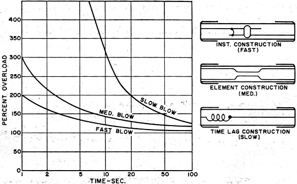
Characteristics of different types of fuses (Electronics World, 1965)
Slow blow fuses are useful in applications where large transient currents are expected like in circuits that power large induction motors. There is a surge when the motor starts, but there is no risk of the wiring supplying the motor overheating as long as the surge is limited in duration. Slow blow fuses work by adding heat capacity to the fuse element. This is often done by thermally bonding an electrically non-conductive material to the fuse element like a ceramic tube.
Fast blow fuses are useful where the goal is to protect a piece of equipment that should never draw large transient currents. Keeping the heat capacity of the fuse element to a minimum and reducing the melting point of the fuse element helps achieve that need.
Summarizing the above: Four factors determine the current rating of any fuse:
- Resistance
- Heat Capacity
- Melting Point
- Heat dissipation
There isn't a neat closed form equation for how long it takes for a fuse to blow because resistance and heat dissipation are both very non-linear terms. As a fuse heats up, its resistance increases which forms a positive feedback loop. On the other hand, as a fuse heats up, the radiative heat transfer of the fuse element to the surrounding environment increases proportional to the fourth power of temperature. There is also conductive cooling which is proportional to temperature and convective cooling. If, however, you neglect heat dissipation and treat resistance as constant, you can simplify the calculation significantly. This is reasonably true for large overcurrent events, and this is where a common fuse characteristic called I^2T (Amp-squared-seconds) comes from.
Current Rating
Typical commercial fuses have current ratings such that they will not blow if operated at their rated current indefinitely. Customers are far more likely to complain that a fuse blows before its rated current than itf it blows at 1.5x its rated current. How much margin a fuse manufacturer will build into their ratings appears to depend on how much thermal conductivity can change based on end application.
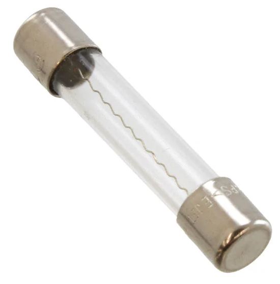
Bel Type 3AG Glass Tube Bodied Fuse
Take, for example, this glass tube bodied fuse. It has pretty good thermal isolation between the ends of the fuse and the center of the fuse element. The current required to blow the fuse will not change significantly whether the customer connects the fuse in line with 26 AWG wire or if they connect it directly to solid copper bus bar. The manufacturer states that the duse will blow in a maximum of one hour at 135% rated current.
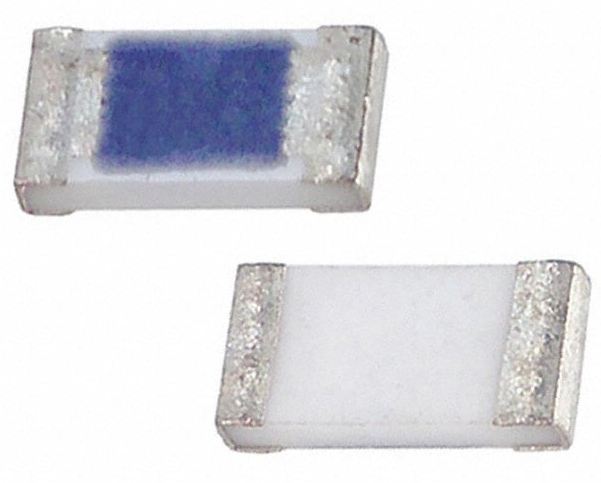
Bel Type C1Q 1206 Package SMD Fuse
Now, consider a 1206 package SMD fuse. There is minimal isolation between the leads of the part and the fuse element. This means that differences in board layout such as connecting the fuse in line with a 6-mil trace vs. connecting it between two 2-oz. planes will change the time to blow. This fuse makes no promises of its maximum time to blow under 200% of its rated current. These differeneces in thermal isolation directly influence the heat dissipation capability of the fuse (point 4 in the section above).
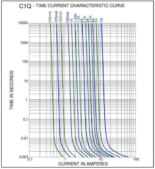
Time to Blow Characteristics for Bel Fuse Type C1Q
Design
I designed two boards which each contain an array of fuses with 5, 6, 8, and 10 mil (thousandth of an inch) trace widths. The first board had three different trace meander options with no solder mask, and the second board had the best meander option from the first board both with and without solder mask. I decided to study the 1206 form factor since it is the most common package for 3-10A rated surface mount fuses (there are 190 in-stock 3-10A 1206 fuses on Digi-key, but only eight 0805 options and 116 0603 options) and because it provided reasonable room to construct the fuse trace. I placed the fuse element between the pads of the 1206 so that a blown trace fuse could conceivably be replaced by a soldered in fuse.
The test PCBs had these characteristics:
- Two Layer PCB with Ground Plane
- 1.6 mm thick
- 1 ounce finished copper
- HASL finish
- Fabricated by JLC PCB
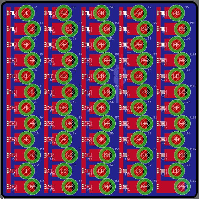
Test Board
The first three rows of fuses on the test board are 5-mil, the next three are 6-mil, the next 3 are 8-mil and the bottom 3 are 10-mil. The three columns to the left are soldermask covered fuses and the two columns to the right are bare fuses. I ordered 10 boards from JLC PCB for a total of $2 not including shipping, so I was able to test each soldermask covered fuse as many as 90 times and each bare fuse as many as 60 times. Since a fuse can inherently only be used once, many fuses are required to get the overall time to current characteristics of a particular type of fuse.
The Best Shape
The three configurations on the first board were:
- A trace directly between the pads.
- A trace with a meander from one side to the other.
- A trace with two meanders.
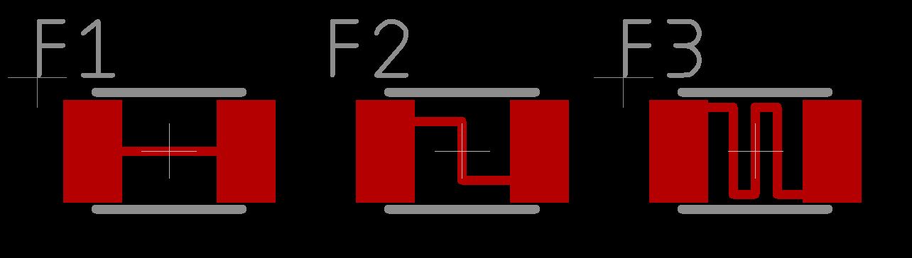
Three types of fuses tested
Unsurprisingly, the most meandered trace required the lowest current to fuse. The direct traces were able to sink quite a bit of heat into the adjacent pads which made their blow times unpredictable (more like slow blow fuses), and the amount of heat that could be generated without blowing the trace was concerning. It was quickly apparent that the most meandered fuse would have the most consistent results because it was the most thermally isolated. This allowed the center of the fuse element to get much hotter than the ends and reach its melting point more quickly.
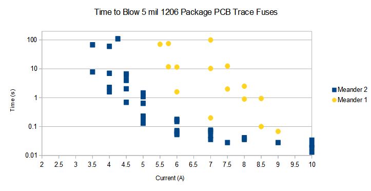
Time to Blow Comparison for a Single Meander (M1) and Two Meander (M2) PCB Trace Fuse
I did not collect detailed information on the straight fuses, but I expect them to behave similar to the single meander fuses but with a somewhat higher current rating.
Soldermask
The first test board had soldermask removed over the fuse element. I observed that some boards had consistently higher times to blow at a given current and thought that this might be due to variation in the thickness of the HASL (hot air level solder) finish. To test this, I included both exposed and solder mask covered fuse elements on the second test board.
What I actually found was that there was still board to board variation when the traces were covered in soldermask which lead my to determine that the differences in time to blow were due to minor differences in plating thickness between the boards. When a PCB is manufactured, it is either pattern or panel plated to add copper to the vias. Differences in where a board is in the plating bath, time in the plating bath, and strength of the plating bath results in differences in thickness. While this mar be within tolerance for a board, it results in measurable differences in the time to burn for these fuses.
Variation in time to blow between boards of the same lot
Solder mask did not make the fuses burn more consistently, but it did increase the time to burn for the fuses by adding heat capacity. As the soldermask heats up, it starts to char and vaporize. This removes heat from the fuse element and results in a longer time to burn and more heat transferred into the laminate under the trace. This is not desirable because it turns out that the laminate becomes conductive when it chars and can cause the circuit board to catch on fire under sustained overcurrent events.
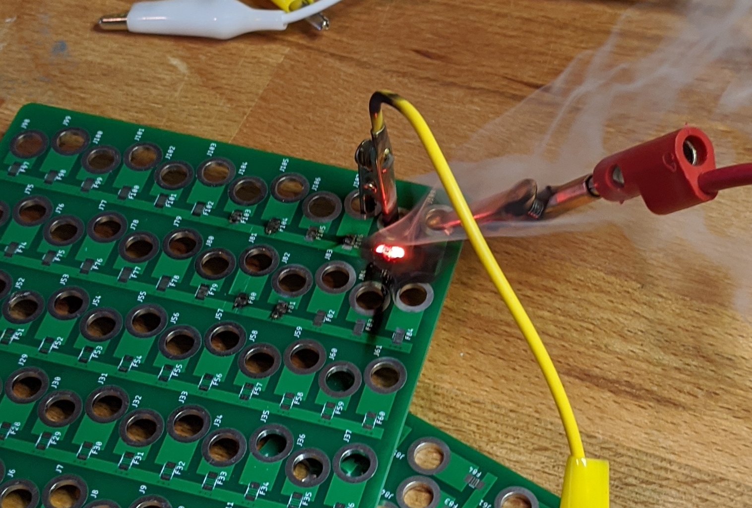
Catastrophically failed PCB Trace Fuse
While I only ever saw catastrophic failure in 8-mil and 10-mil bare fuses, I saw catestrophic failure in all widths of soldermask covered fuses:
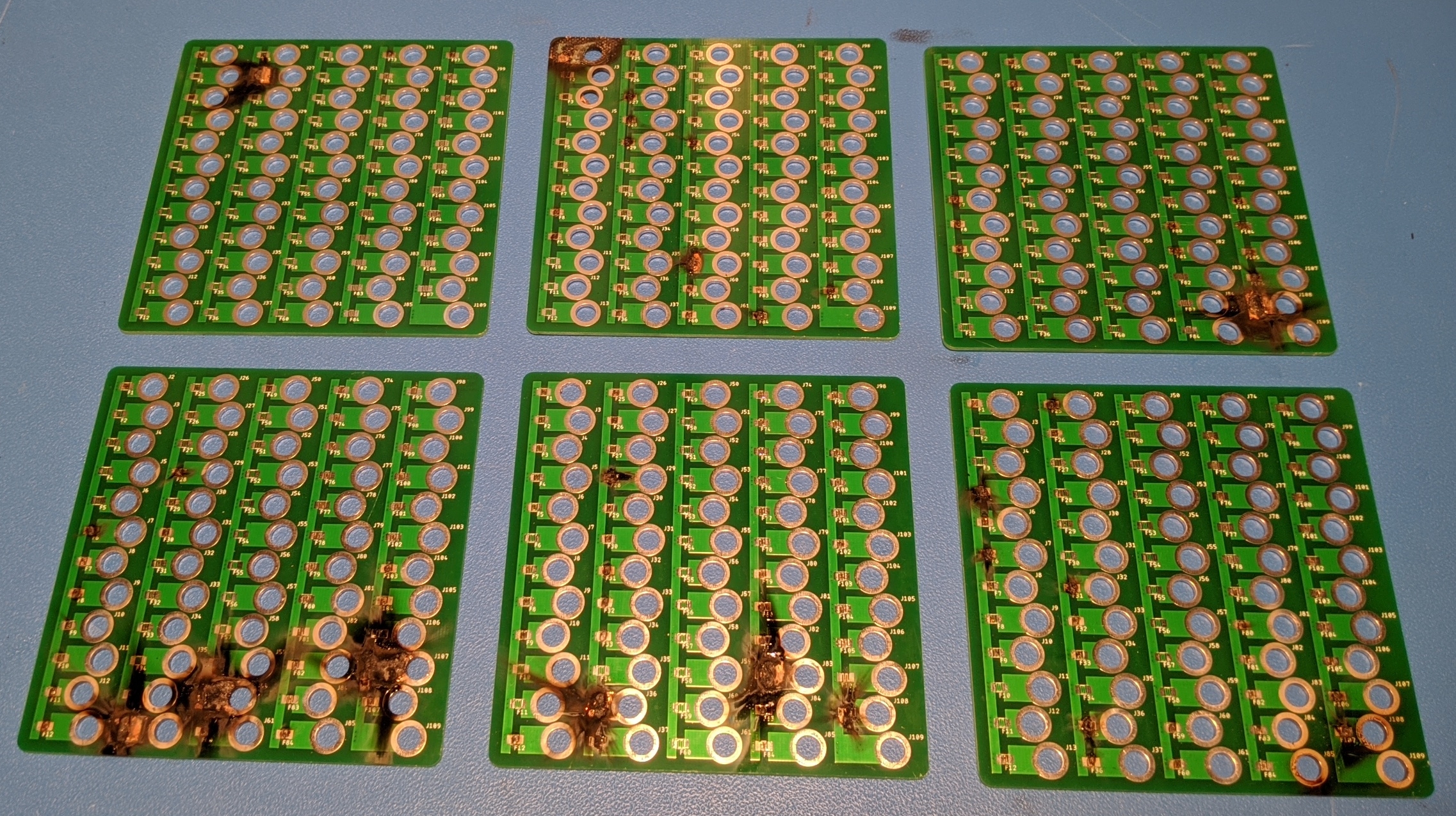
Runaway fuses
Test Setup
To get the current vs. time to blow for each fuse, I had to test test multiple fuses of the same type at a variety of different currents. By plotting many individual tests together, the overall curve becomes apparent. I supplied a constant current to the fuses using a power supply in constant current mode. Constant current power supplies do have some output cap, though. I was not able to plug a fuse board directly into a power supply that was already on since its output cap would supply enough current to flow smaller fuses as it discharged. I resolved this issue by keeping the power supply shorted though a jumper in parallel with the fuse under test. To initiate the test, I removed the jumper and waited for the fuse to blow. I then reinserted the jumper before hooking up the next fuse.
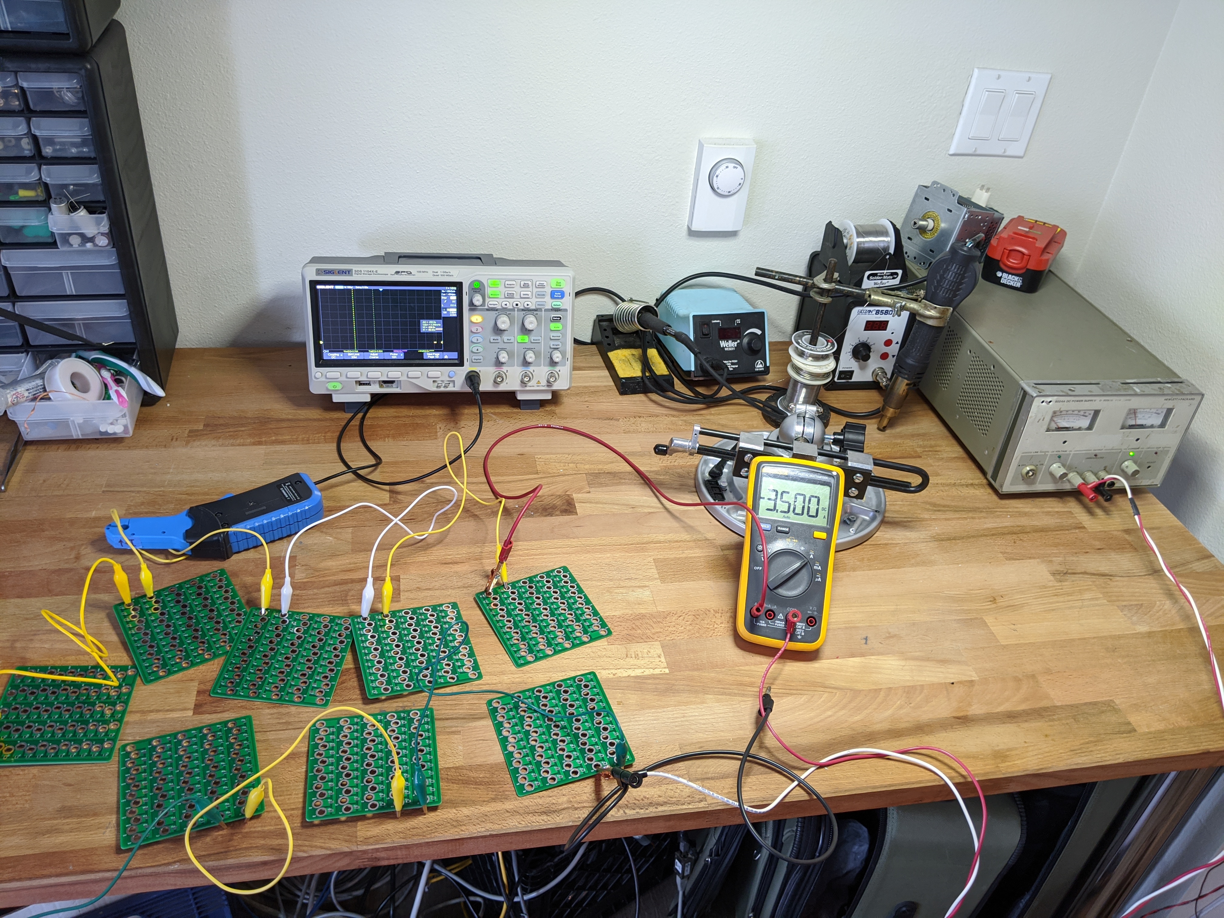
Test setup
I monitored the current set point using an external fluke multimeter since the display on my old HP supply is best considered "for indication only." To get the precise time it took for the fuse to blow, I also monitored the current with a current probe connected to an oscilloscope in roll mode. The "width" measurement on my Siglent SDS 1104 oscilloscope did a great job of automatically measuring the duration of the current pulse through the fuse, so I fortunately did not have to use manual cursors for these measurements.
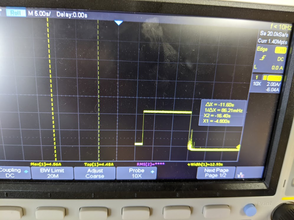
Oscillogram of Current Though a Fuse
Results
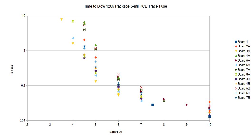
Unless otherwise indicated, all of these plots are for the fuse type with two meanders (F3). These include data from both the first and second test boards which is why there are points on some charts that do not appear on others. The spreadsheet used to generate these plots can be found here.
The 'Theoretical' trace found on some of these plots is from equation 6 in the Brooks and Adam paper: t =0.0346*(A/I)^2 where t is time to blow, A is crossectional area of the fuse in circular mils, and I is current. As expected and as shown in that paper's simulations, the actual time to blow is much longer for actual trace fuses due to heat dissipation.
Current Rating
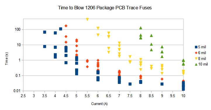
I based the 'current rating' of these fuses off of the current it took them, on average, to blow in five seconds. I then assumed that current to be 200% of the rated current of the fuse.
Comparison of Different Trace Widths for PCB Trace Fuses Without Soldermask
| Trace Width | Current Rating |
|---|---|
| 5-mil | 2 A |
| 6-mil | 2.5 A |
| 8-mil | 3.5 A |
| 10-mil | 4.5 A |
I2T Rating
As expected, the I2T value stabilizes with higher currents since there is less time for heat to be dissipated before the fuse blows:
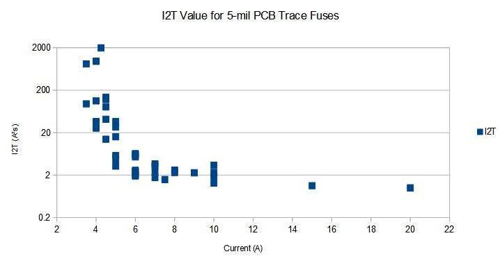
Calculated "I2T" Values for 5-mil PCB Trace Fuses
Fuse Shape
More meanders provide more thermal isolation and more consistent performance:
Time to Blow Comparison for a Single Meander (M1) and Two Meander (M2) PCB Trace Fuse
Soldermask vs. No Soldermask
Soldermask on fuses increases the time to blow and makes time to blow less consistent.
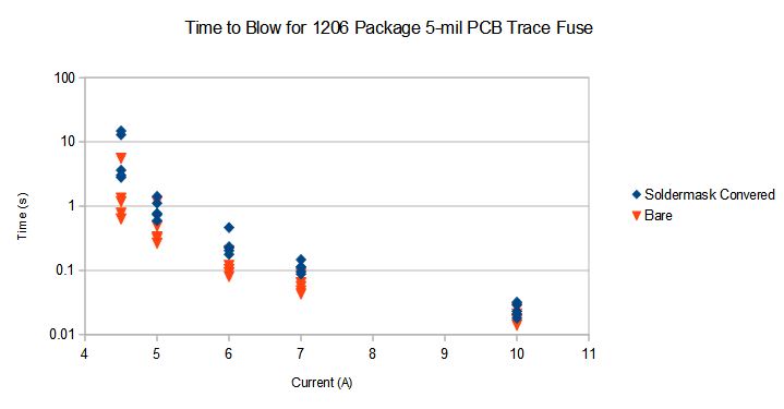
5-mil PCB Trace Fuses With and Without Soldermask
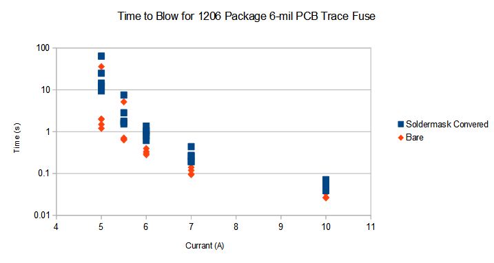
6-mil PCB Trace Fuses With and Without Soldermask
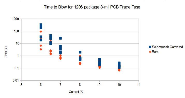
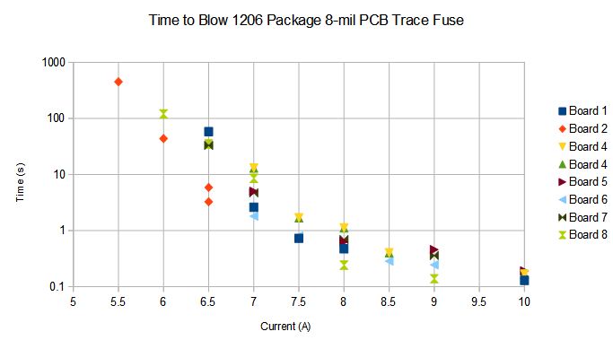
8-mil PCB Trace Fuses With and Without Soldermask
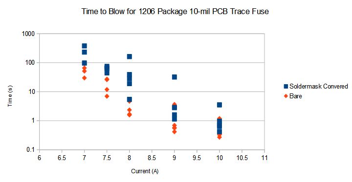
10-mil PCB Trace Fuses With and Without Soldermask
Board to Board Variation
These plots show the trends in fuse time to blow between different boards. The plot with two different lots shows that, at least for these two lots, show no real differences between the two lots: board to board differences dominate. The first 'lot' is the first test board design with different shapes and the second 'lot' is the second test board design with only meandered traces both with and without soldermask.
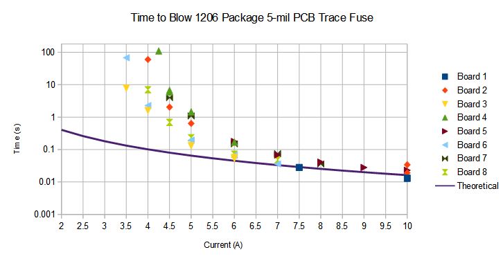
Board to Board Variation of 5-mil PCB Trace Fuses
Board to Board Variation of 5-mil PCB Trace Fuses from Two Different Lots
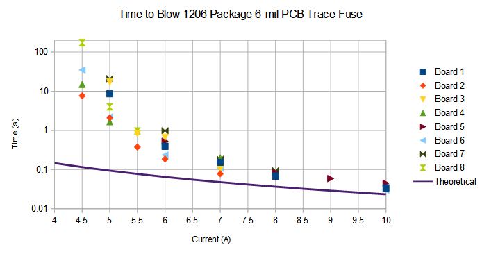
Board to Board Variation of 6-mil PCB Trace Fuses
Board to Board Variation of 8-mil PCB Trace Fuses
Conclusion
I do not believe that trace fuses are a suitable replacement for discrete fuses in most applications. You need to understand the failure modes you are trying to protect against before trying to use them. Adding a 2A trace fuse to the sense input of a battery protection IC is reasonable because that IC should never draw more than a few tens of microamps. If FOD or incautious handling results in a battery sense short, a trace fuse will quickly pop before the rest of the trace is damaged. Trace fuses are also reasonable in crowbar protection circuits like reverse battery connection circuits since the battery will very quickly blow the fuse.
Trace fuses are not well suited for limiting the current available to subcircuits. If you have a board that outputs, say, 5V from its on-board 10A 5V supply, it would not be a good idea to use a 2A PCB trace fuse to protect that output. If a load of 3A were applied, it may take hours or months before the fuse blows -- if it ever does. In the meantime, it may be thermally degrading the laminate under it and setting up a situatio that could result in a fire.
Straight PCB trace fuses (fusible links) are worthy of more study since they may be less prone to causing fires than these meandered trace fuses. Their downside, as covered above, is a less consistent time to blow, but whether or not that matters depends on the application.
Videos
Here's a soldermask covered 5-mil fuse blowing quickly:
Here's a soldermask covered 5-mil fuse slowing catching on fire:
Here's a bare 8-mil fuse blowing with the CC-CV supply set to 60V: