DNVT Test Boards
2023
I designed two test boards before moving on to the full four-phone switch. The first test board uses an STM32F103 Bluepill development board, and I designed the second test board for use with a Raspberry Pi Pico after Nick and I discovered that the Pico has periferals much better suited for differential Manchester encode and decode. I didn't know if I would even be able to get simultaneous encode and decode working on the STM32, but the the RP2040 on the Pico can handle encode and decode for four phones while barely loading one of its two cores.
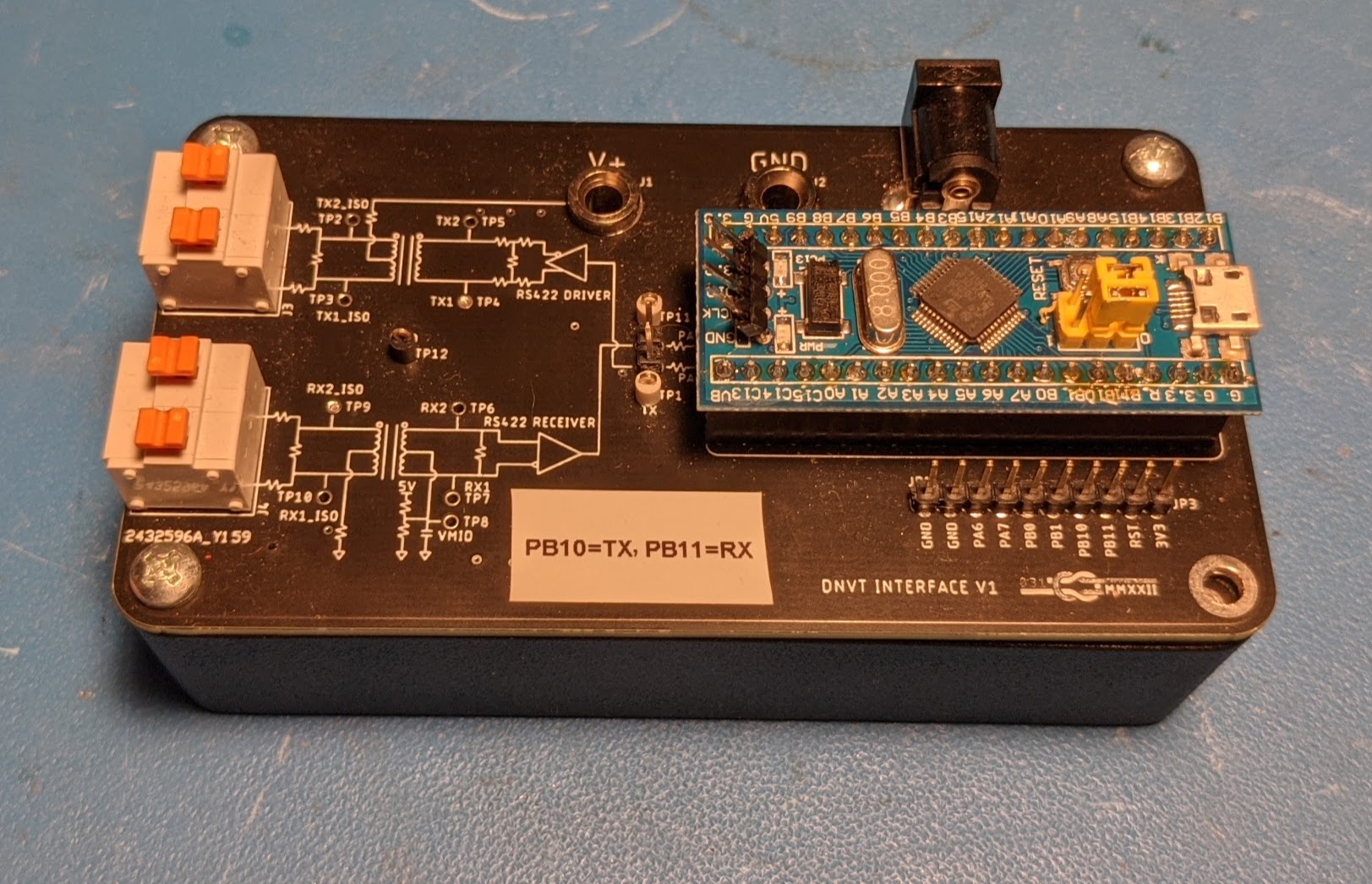
STM32 Blue Pill DNVT Interface Board
I used these test boards to determine which control codewords corresponded to which functions as well as the required sequencing of these codewords to set the phones to their various states. Nick used this information up a state machine on the Pico to handle all the functions of a switch.
Construction
I designed both test boards to fit on top of Hammond 1590B project boxes. I had fun with the silkscreen and put a rough schematic on the top side and put all of the active parts on the bottom side of the PCB. The power input for the phones supports both banana plugs and DC barrel jack, and the connection to the phones is made with some nice spring lock wire to board connectors that I found. Aside from the physical inerface to the phones detailed on this page, there isn't much else to the boards aside from connecting to and breaking out IO from the Bluepill / Pico boards.
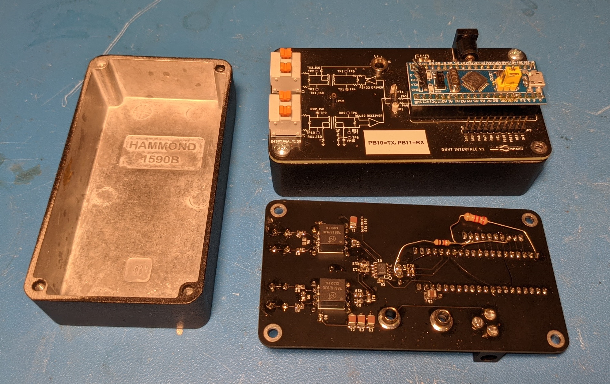
Inside of Interface Board Box
I made two mistakes on the first interface board: I connected the 5V RS422 transceiver IO to STM32F103 pins that are not 5V tolerant, and I did not break out the PA9/PA10 serial serial interface. I originally selected a 5V RS422 driver so that I wouldn't load the tiny 3.3V regulator on the Blue Pill. The Raspberry Pi Pico has an on-board buck converter, so I switched to a 3.3V RS422 driver on the second revision. To resolve the issues with the first board, I jumpered the IO from the RS422 transceiver over to spare pins and added a resistor divider to handle the IO voltage mismatch.
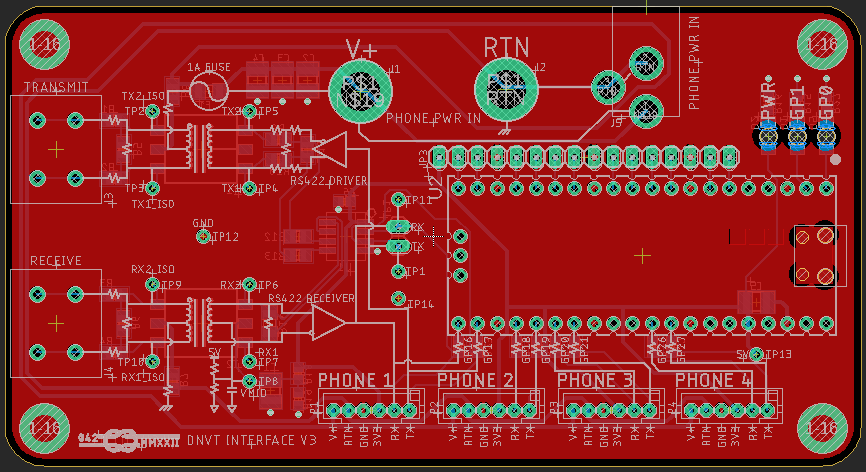
V3 Pico Interface Board Layout
The Raspberry Pi Pico version of the board is labled V3 because I started on a version two of the Blue Pill based board that I never ordered after discovering the RP2040. Aside from changing microcontrollers, I also added status LEDs, an input fuse, and JST-PH connectors to allow multiple boxes to be slaved off of one master. The PCB design files and schematics for all of these boards can be found here.
Codeword Reverse Engineering
Before discovering the Raspberry Pi Pico, my best bet for a microcontroller to handle differential Manchester encoding and decoding seemed to be the STM32F103 due to its capable timer periferals. After determing that the physical interface worked and that I was seeing received data at the RS422 receiver, I captured on an oscilloscope the first few thousand bits transmitted by the phone when it was taken off-hook in LB (Local battery) mode. I then used a Python script to decode the capture and see what was going on.
Some background on the expected operation of the phones: In LB mode with two phones connected together, the called party start ringing as soon as the calling party takes their handset off-hook. This is accomplished by the calling phone sending the ring codeword some hundred times. The called phone then rings until it is taken off hook or the calling phone is hung up. When the calling phone hangs up, it sends a codeword to stop the ringing of the called phone. If you disconnect the calling phone from the called phone before hanging up the calling phone, the called phone will continue to ring indefinitely until it is picked up because it has no easy of receiving the stop ring codeword.
I started with only one TA-1042 DNVT and planned to start by playing whatever the phone sends in LB mode back to it. My first attempt at playing the python script decoded codewords back to the phone was unsuccessful, though. Instead of using a timer, I used Arduino delayMicroseconds() which aparantly had too much jitter — or something — for the phone to accept the data. That was not obvious at the time, so in order to see if I was missing something fundamental or if the phone was defective, I ordered a second phone from eBay. I also tried playing data back to the phones with my SDG2042X function generator, but I discovered that the USB port on on mine was broken. I attempted to use it over USB, but I couldn't get the sample timing to work out correctly, so I gave up on that approach.
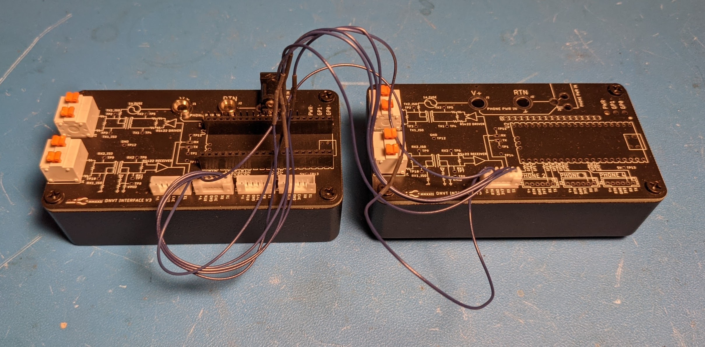
Back-to-back Interface Boards Intercepting LB-mode Phone Call
I proved that there was noting wrong with the phones or my interface boards by connecting two interface boards back-to-back between the two phones. Each received the differential signal from its respective phone and then passed the 3.3V logic level signal to the other interface board for re-transmission. I was also able to power the phones using the interface boards common battery style despite the selector switch on the phones being in LB mode. Knowing now that the re-encoding of the decoded data should be working, I rewrote the code to use a timer. This worked! I was able to ring the phone finally. The ring codeword was even the same in LB and CB mode.
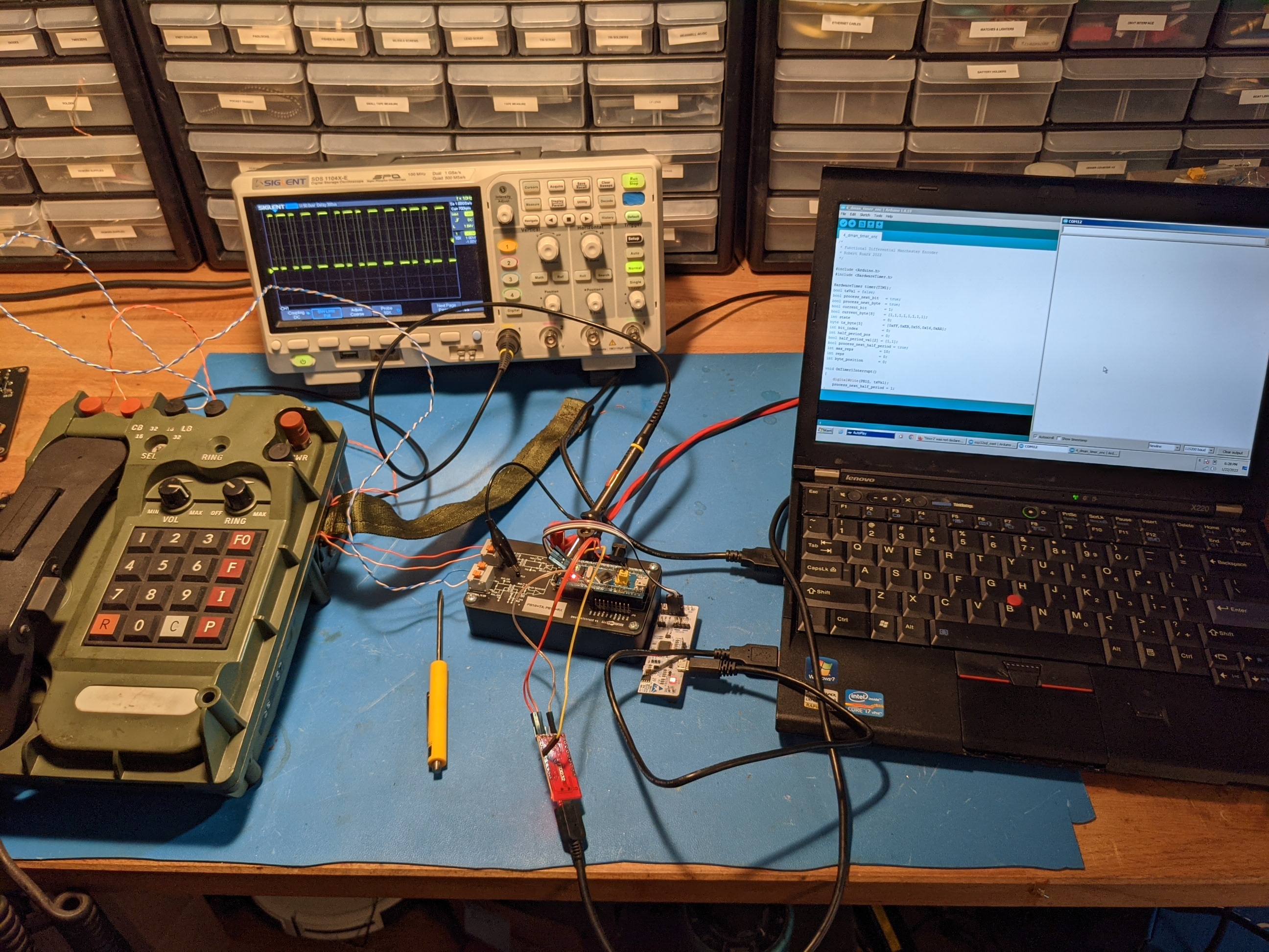
STM32 Interface Board Codeword Reverse Engineering Setup
The next step was trying to get the phone into dial mode. I set the STM32 up to accept two numbers over the serial interface: which codeword to send and how many times to repeat it. Initially, the interface board stopped transmitting after sending the codewords. I thought the phone would drop into dial mode after receiving the correct codeword enough times, but it did not. I went through every possible codeword and could not get it to enter dial. After a couple days of thinking about what could be going wrong, I figured that one thing I could do to better emulate a real switch would be to send a dial tone after sending the test codeword. To approximate a dial tone, I went with a hand coded sine wave at 1/32 (500 Hz at 16 kHz line rate) the line rate: 0xEB5514AA. I went back through the 20 possible codewords, and finally got the phone to enable its dial!
The next challenge was to get the phone back into traffic mode to pass audio. This was also frustrating because it took two consecutive codewords. After finding the few codewords that put the phone into a different state from dial mode, I went one by one and tried the remaining 19 codewords. I finally settled on the right combination and had the phone in traffic mode. The same two codewords (GO TO PLAIN TEXT followed by LOCK IN ACK) ended up being the sequence needed to put a called phone into traffic after the called party takes the phone off hook. The final codeword needed for a minimum viable switch was the RELEASE ACK codeword which the switch sends the phone to acknowledge that it has been placed on hook. There are definitely other functions (such as changing phones from 32 kHz to 16 kHz) that I haven't sorted out, but I'm happy to have the phones in a functional state.
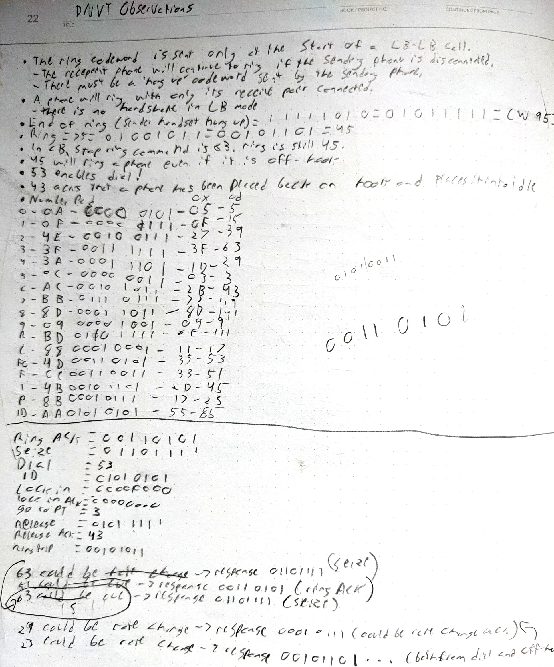
Codeword Reverse Engineering Notes
So far I have just mentioned the codewords sent by the switch to the phones. In every state aside from traffic, the phone is also sending codewords of its own to the switch. Since my STM32 code can't simultaneously handle encode and decode of Differential Manchester, I was just sending codewords to the phones to force them into my desired states without listening to what they were seding back. Instead of setting up a second board to decode the codewords sent back by the phone, I hooked the receiver output into my oscilloscope and decoded the data by sight. Decoding Differential Manchester by sight is probably one of my least useful skills, but its actually pretty easy. You just look for the long and short periods. Using tis method, I wrote down all the codewords in my notebook and produced the state diagrams on this page.
I was able to get 16 kHz decoding working on the STM32, but I was not able to get serial output at 32 kHz because I had to run interrupts at 64 kHz. The only use I got out of the code was capturing traffic during a normal phone call as an input to decoding CVSD using python.
Raspberry Pi Pico
At this point, Nick became actively involved in the project. Differential Manchester is literally an example use case of the PIO blocks in the RP2040, so Nick very quickly had phones ringing, dialing, and playing back audio. This was initially done with a Raspberry Pi Pico board jumper wired into the socket for the STM32 Blue Pill. After about a week, we hooked up a second interface board to the same Pi and completed out first real call.
Raspberry Pi Pico Interface Board with Slave Board
We used the Pico Interface Board for a few weeks before I designed and ordered the real switch. It turns out that the pre-wired JST cables on Digi-key invert their pinout from end to end, so I had to the them in half and solder them back in the right order. Ultimately we got little use out of this revision of the interface board and quickly moved on to the four-phone switch.