Geiger Counter Improvements
2024
Design Documents & SoftwareThe first version of my Geiger counter board has one obvious limitation: it is USB powered and can't be used without an external power source. I added an internal 18650 cell lithium ion battery in the second revision. This worked fine, but I wanted to add support for Geiger tubes beyond SBM-20 and also wanted to upgrade to a through hole USB-C connector after ripping the surface mount micro-USB connectors off of the board by accident more than once. In addition to supporting more Geiger tube sizes and adding a more rugged USB connector, I also updated the design for automated assembly by JLCPCB so that I could have a few spares without spending all day soldering.
Final Geiger Counter
I was inspired to finally complete this project after coming across radiological contamination area under the McKinley bridge in St. Louis Missouri next to Mallinckrodt. I didn't have to go out of my way to find this; it was literally in the middle of the bike trail which has now been routed around it. Significant quantities of Uranium ore were processed in St. Louis at Mallinckrodt Chemical Works in support of the Manhattan Project, and the site I came across is between that facility and the Mississippi river.
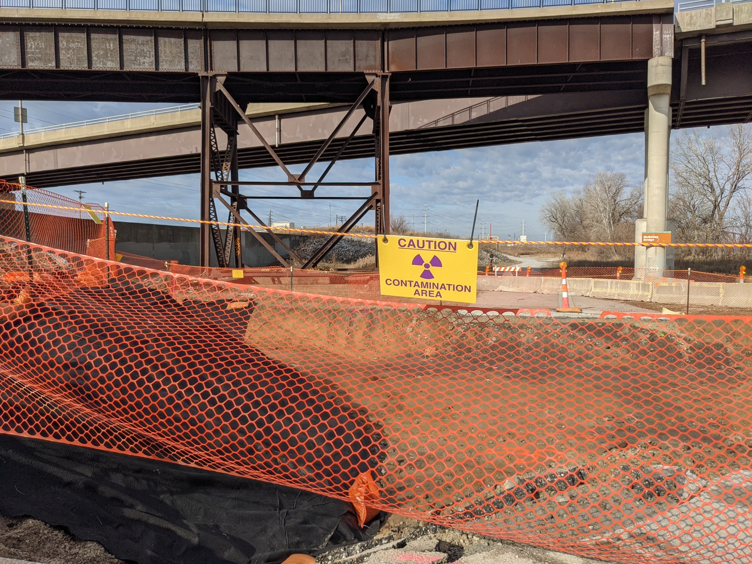
Open Air Radiological Contamination Pit Near St. Louis Mallinckrodt Facility
I couldn't find any local news articles about this, but I also came across zero other people on my nine mile ride on the riverfront trail between the Old Chain of Rocks Bridge and the contaminated site. Anyway, here are the details of the design changes.
Version 2 Design
I completed V2 near end of 2022 and V3 at the end of 2023. V2 was the first battery powered version of the Geiger Counter, but it left a few things to be desired.
Changes:
- Added an 18650 battery holder.
- Added a power switch.
- Added a battery charge IC and undervoltage protection.
- Added overvoltage protection circuit to Geiger high voltage supply.
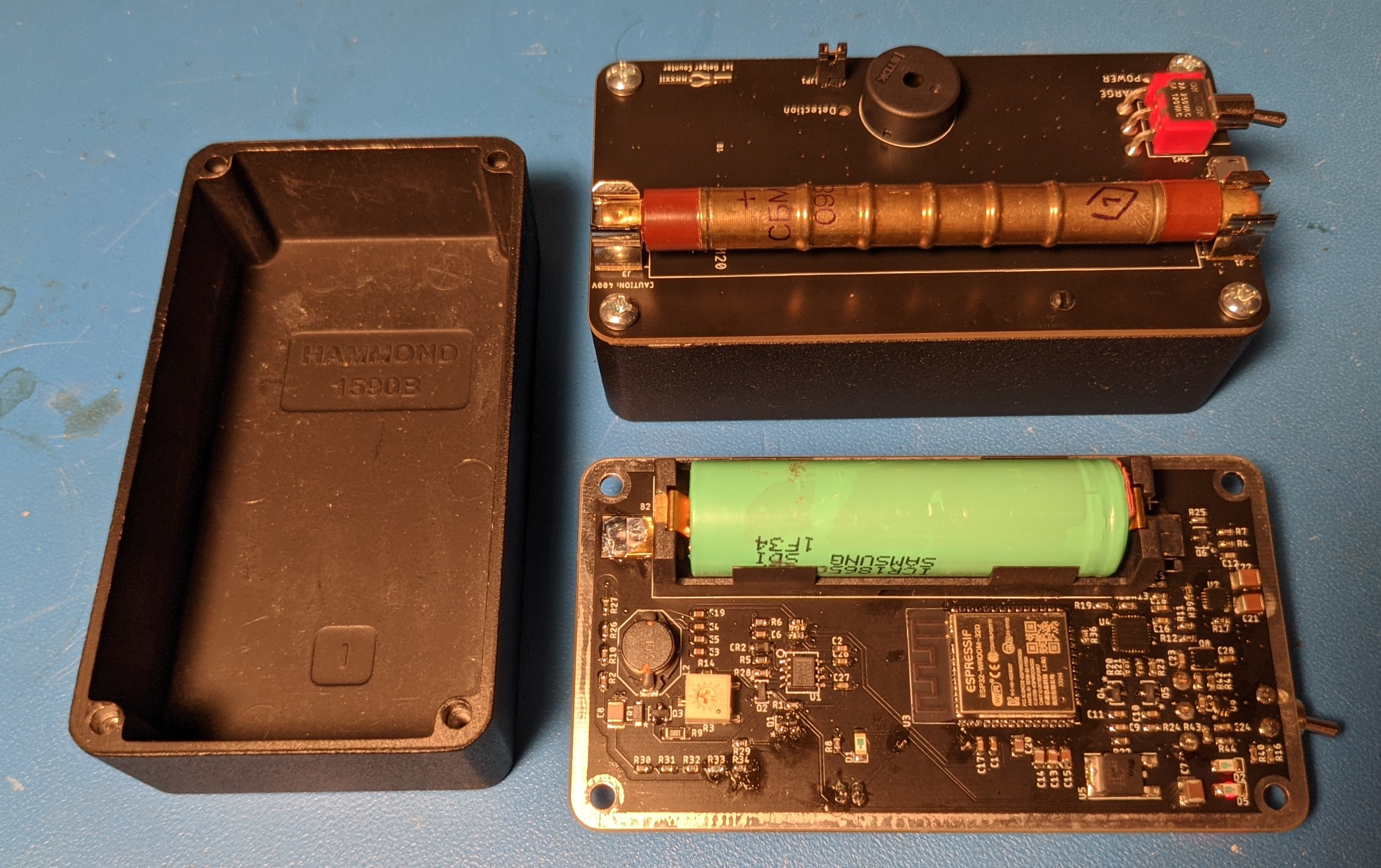
Finished V2 Geiger Counter
Power
I've designed a several lithium-ion powered boards before that use buck-boost converters to power their 3.3V microcontrollers, but here I was lazy and powered the 3.3V ESP32 with a low dropout linear regulator connected to the battery. I set an undervoltage protection limit of 3.2V (the ESP32 will get squirrely as you undervolt it) which results in something like 70% of the capacity of the lithium-ion battery being useable. My laziness was driven by the integrated buck-boost part that I had used in the past being out of stock and subsequently not feeling like finding a new part and adding it to my library.
There was no need for a power switch on the previous since it was USB powered, so I had to add one now that the unit is battery powered. I used a right angle switch from the 100 series of E-Switch. These are pricy (like most pieces of electromechanical hardware) but are great quality and are available in many different configurations (mounting options, poles, momentary).
Battery Charge and Protection
Lithium ion battery require voltage and current protection for reliable and safe operation. You need to ensure that the voltage, current, and temperature limits of the battery are not exceeded. For current limits, I added a PCB fuse since the only situation where discharge current 100mA would be expected is short circuit, and the linear battery charger IC I selected sets the charge current limit. I ignored temperature limits which is not uncommon for low power products with slow charging circuits like this. Even if the board is left in the sun while charging, nothing should get hot enough to actually be dangerous. For voltage protection, the linear battery charge IC sets the maximum voltage and a comparator based under voltage protection circuit protects against over discharge.
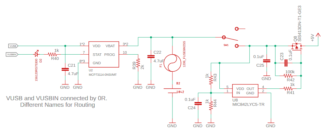
Battery Charge and Protection Circuits
MCP73114-0NSI/MF is a battery charger IC well suited for charging lithium ion batteries off of a 5V source. It provides a charging indicator light and has a resistor programmable charge current limit. In this case, I set the charge current to 500mA so that the IC didn't get too warm and so that I wouldn't have trouble charging off of typical USB ports. While the USB spec specifies that standard USB 2.0 peripherals can only draw 100mA without further negotiation, only a bottom-tier OEM would design a USB port not capable of supporting 500mA these days due to the proliferation of non-compliant USB accessories. The '-0NS/MF' at the end of the part number sets the charge voltage to 4.2V.
An open drain comparator with an internal reference (MIC842LYC5-TR) controls a P-channel MOSFET acting as a high side switch to enforce an undervoltage limit on the battery. The internal reference is nice here because it both eliminates an external reference part and also ensures low quiescent current: cheap shunt voltage references require significant bias current, and low quiescent current series voltage references are more expensive. I set the undervoltage limit to about 3.2V (the schematic does not reflect what I ultimately came up with on the bench).
Boost Converter Overvoltage Protection
The output voltage of the high voltage supply for the Geiger tube is nominally set by the peak current of the inductor triggering reset of the 555 timer by the voltage across a current sense shunt exceeding the base to emitter threshold of an NPN BJT. As simulations for the last board showed, this results in a highly temperature dependent output voltage. This alone is OK, but because the output voltage needs to be adjusted with a potentiometer, the potential exists to set the output voltage too high (in excess of the rating sof the diode and BJT). In practice, it seems that non-destructive breakdown mechanisms in these parts limit the output voltage, but this is achieved by operating the parts past their absolute maximum ratings which is never good to bank on. To add some protection against this, I added a second reset NPN with its base connected to a voltage divider from the output. The voltage divider adds a load to the output, but this actually stabilizes the output voltage somewhat since with no-load the output voltage is defined by the switching losses and diode leakage (which will be temperature dependent) only. I set this limit to 500V to provide plenty of headroom above the nominal 400V output.
Version 3 Design
V3 is the final version that I completed at the end of 2023. It is optimized for JLCPCB assembly and supports multiple sizes of Geiger tubes.
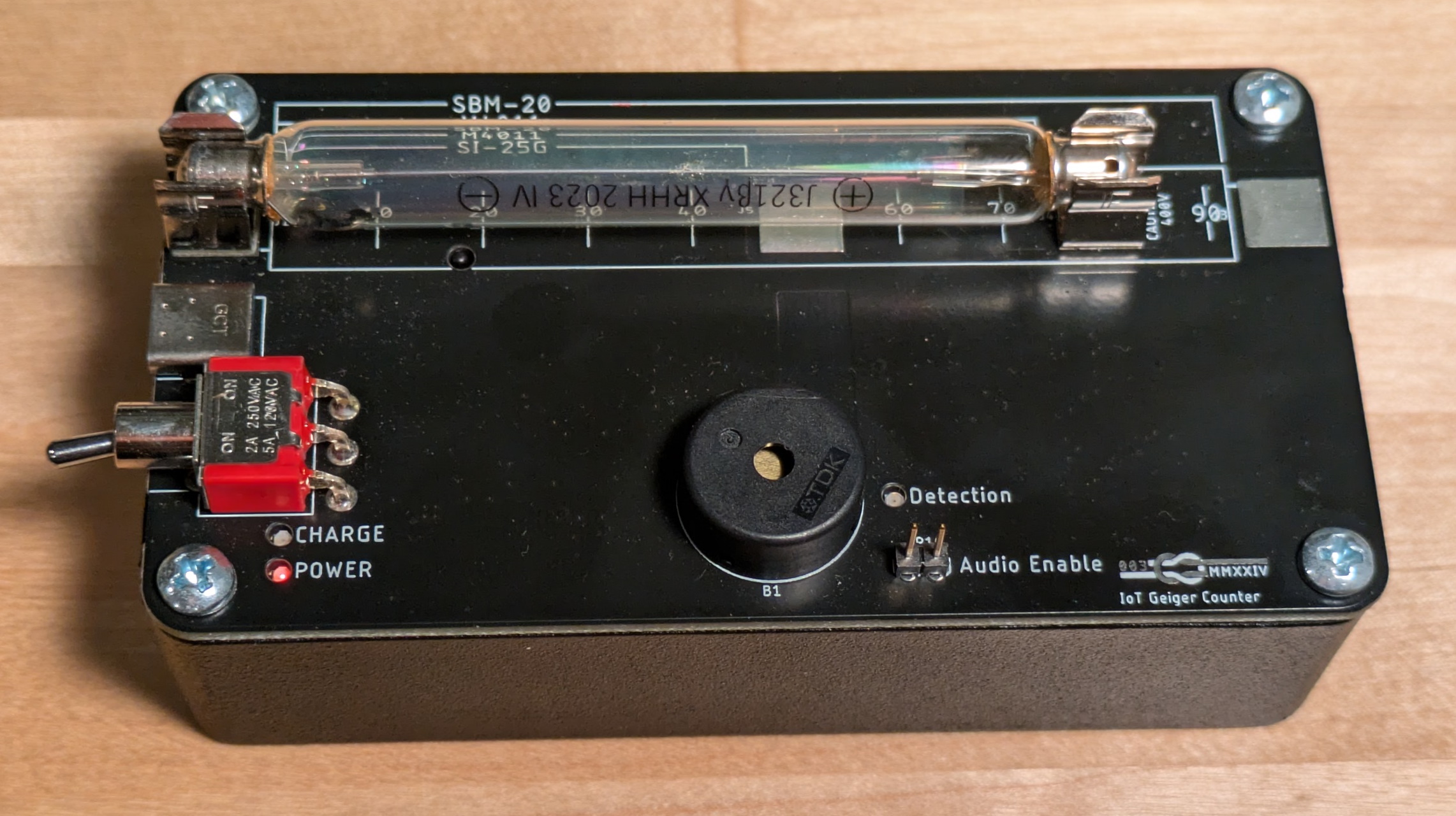
Finished V3 Geiger Counter
Changes:
- Added buck-boost regulator.
- Changed battery charge IC to a cheaper option.
- Changed the battery protection circuit to a cheaper option.
- Optimized for parts supported by JLCPCB assembly.
- Changed USB connector to USB-C.
- Added support for different length Geiger tubes.
One goal of this version of the Geiger counter was to have as many parts installed by JLCPCB as possible. I ended up only needing to install:
- The through hole USB-C connector.
- The through hole piezo buzzer and header.
- The power switch.
- The fuse holders.
- The reverse mount LEDs.
- The voltage adjustment potentiometer.
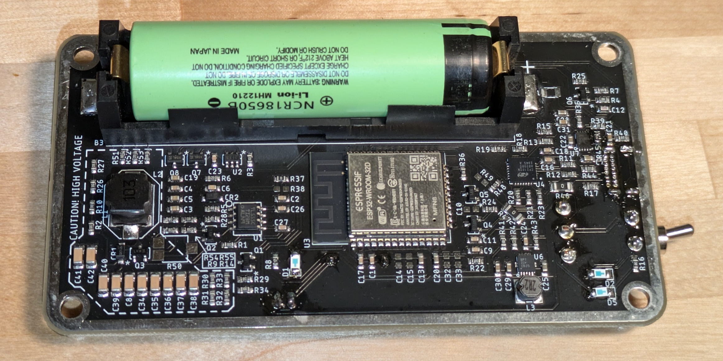
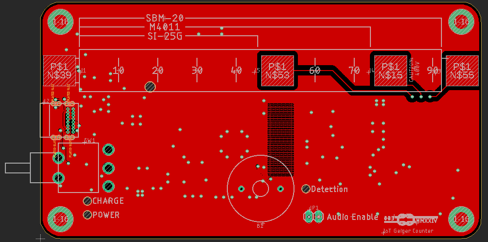
Active Side of V3 Geiger Counter
Power Supply
I had to buy a particularly low drop out LDO for the previous version to have anywhere near acceptable battery life — I initially bought a woefully inappropriate one and had to perform initial bringup by charging the battery to 3.3V and shorting across the regulator. Given that there isn't a huge cost delta between high performance LDOs and buck boost converters, I bit the bullet and designed in a proper buck boost converter using a part that was in stock at JLCPCB: TPS63000. This part has an input range of 1.8-5.5V which is perfect for a single cell lithium ion battery, but (very annoyingly) it does not have a precision enable threshold, so it is necessary to keep an undervoltage protection circuit on the battery.
JLCPCB often has quality TI parts in stock at a price less than western distributors, so I can often get parts assembled on a board for less than it would cost to buy them loose on Digikey. This means that the cost delta between assembling boards myself and having JLCPCB do it is often surprisingly small.
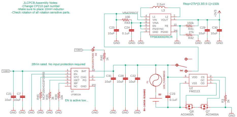
Battery Charge, Battery Protection, and Voltage Regulator Circuits
Battery Charger
Since the battery charge IC that I used on V2 (MCP73114) was not in stock at JLCPCB, I switched to LP28013A ($0.27). I programmed the current to 500mA and called it a day. Or so I thought. The enable pin is active low despite being named "EN" instead of "nEN" or "DIS" as would be expected from a Western semiconductor supplier. I made two mistakes on my first order of V3: I chose green soldermask and I connected this pin straight into the ground plane. This proved to be difficult to rework, so I threw the first order of green boards not capable of recharging in my closet in case we enter the End Times. I will make no further mention of this mistake and will deny the existence of this intermediate version of the Geiger counter outside of this paragraph.
The High Cost of Low Prices
Battery Protection
The undervoltage protection comparator on the previous design worked OK but required manual tuning with questionable performance unit-to-unit, so I added a proper battery protection IC. Since I am using JLCPCB as my assembler, I went with the cheapest protection IC that they have high stock of. This ended up being FM2113 ($0.03) which has a datasheet in Mandarin:
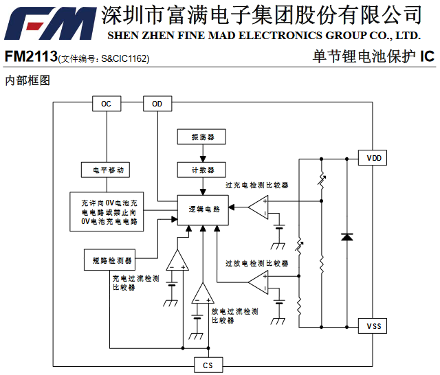
FM2113 Block Diagram
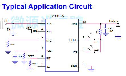
Its kind of fun (type-2 fun — quite frustrating in the moment) to find and implement these kind of parts from JLCPCB. It is actually more challenging to find appropriate parts given JLCPCB's atrocious search interface than it is to implement from a foreign language datasheet. I threw a couple key phrases into Google translate to confirm my assumptions, but for the most part I could make out what I needed to do from the block diagrams and typical application circuits:
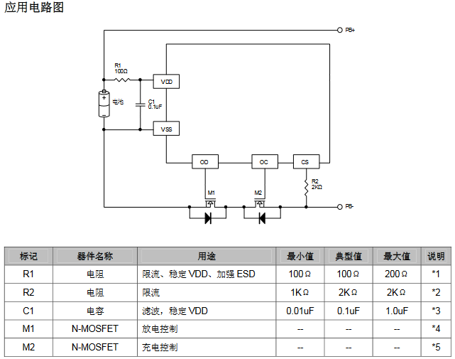
FM2113 Typical Application
Google lens also does a pretty good job at translating text in PDFs and images. Here's its take on the block diagram:
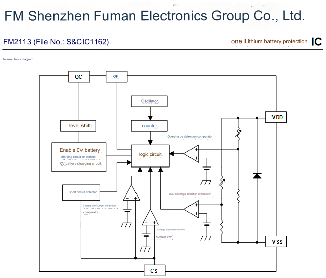
Translated FM2113 Block Diagram
USB-C
The previous version of this board used a surface mount micro USB connector, and I managed to rip one off of a board which required careful rework and epoxy to fix. Through hole USB-C connectors are much stronger and are the future, so I switched to that for this version. For an overview of how to upgrade a micro-USB design to USB-C, take a look at this Hackaday article.
There are two sideband use pins on USB-C connectors which are often used these days to break out a second USB 2.0 pair for debug use. I hooked up the UART TX line (BOM selectable to another GPIO pin) of the ESP32 to the SBU1 pin in case I ever want to interface this board with another of my project boards that doesn't support USB. One possible use case I was thinking about was having the ESP32 output discrete pulses for each radiation event over this sideband interface so that another board with a GPS could associate activity with location to to connect to headphones. USB-C supports analog audio (convenient since cell phones no longer have dedicated headphone ports), but annoyingly the data pins are used to carry the left and right audio. This means that you need to use a MUX part like TUSBA224. I did not implement this on the Geiger Counter board, but it would be a neat additional feature to add.
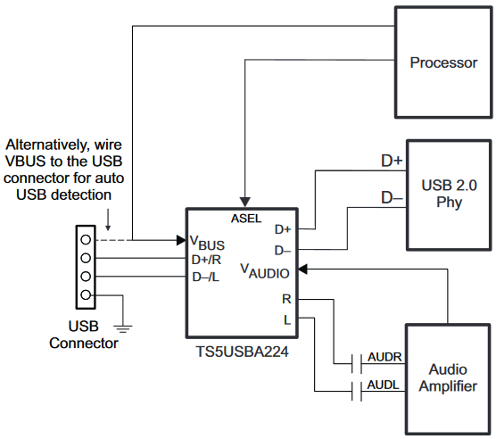
USB Audio MUX Block Diagram
Surface mount micro USB connectors are pretty fragile. I have seen a fair number of >$1000 development boards destroyed after someone snags the USB cable while walking by and rips the connector off of the board traces and all. I had that happen with one of the V2 Geiger counters (and my Nano VNA...) but in both cases I was lucky that there was still enough of the pad on the board that I was able to rework new connectors back on. I secured the new connector with some epoxy, but for V3 I decided to upgrade to a nice sturdy through hole USB-C connector. Since phone chargers have all moved over to USB-C, I think it makes sense to use USB-C on most all newly designed portable products.
Other Tubes
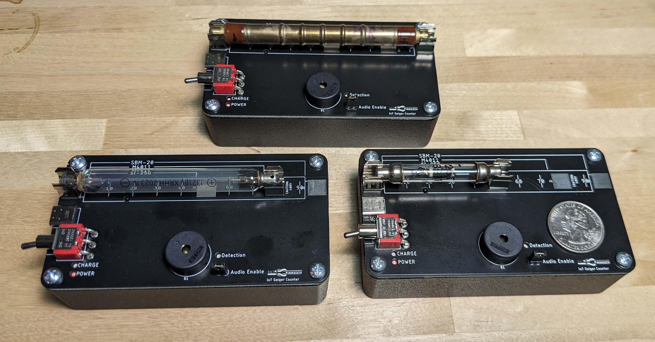
I designed the first two Geiger counters around USSR surplus SBM-20 tubes. These are fragile and aren't being built anymore, so I added support for glass body high rate USSR surplus SI-25G and SI-3BG tubes as well as newly manufactured Chinese M4011 tubes. Since each tube is a different length, which tube the Geiger Counter supports is selected by which fuse holder clips you solder in place.
Three Tube Length Options
Measurements
Converting between counts per minute and dose rate requires knowledge of the source and the counting efficiency of the tube. While nearly 100% of beta particles that get through the wall of the tube will result in a count, as few as 1% of the gamma photons that pass through the tube will result in a count. This is because the beta particle is an electron and itself triggers an avalanche discharge, but a gamma photon must either ionize gas in the tube or cause a secondary beta to be generated in the wall of the tube in order to be counted.
While the SBM-20 tubes have a sensitivity number in their datasheet, I can't find this information for the rest of the tubes. To get a reasonable estimate of sensitivity, I bought a 1 µCi Co-60 source from Spectrum Technologies in Oak Ridge Tennessee. This is an 'exempt quantity' source meaning that no license is required to own it — the official disposal guidance is to deface or remove the label and to throw it in the trash when I am done with it, so its really not that problematic of a thing to have around. Bear in mind that the Co-60 source has a 20% tolerance and these readings will share the same tolerance.
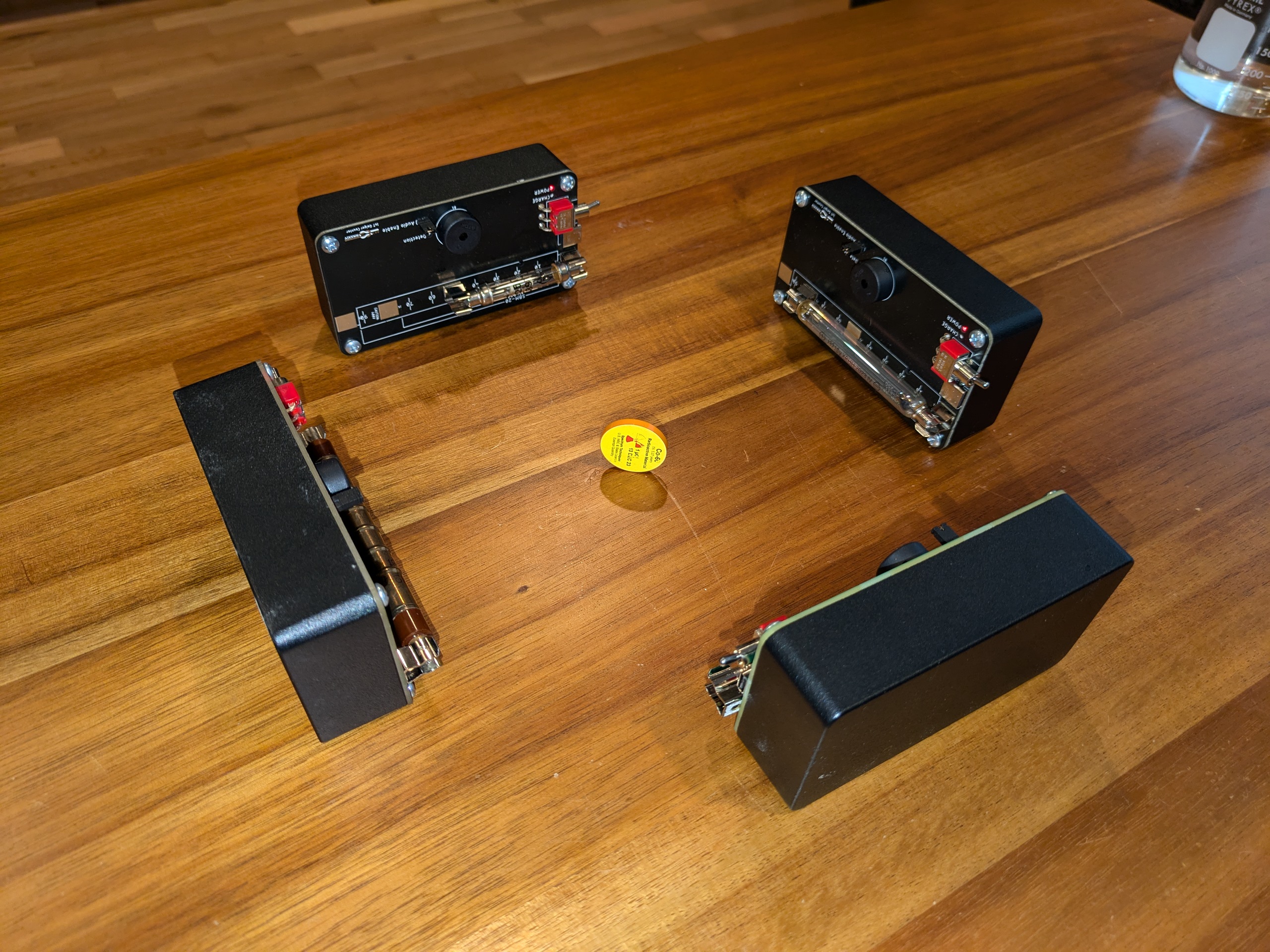
Sensitivity Measurement Setup
To calculate the dose rate at distance from a source, you need to know its activity and gamma constant. The gamma constant of Co-60 is 1.32\(\frac{R \cdot m^2}{hr \cdot Ci}\). The source I used eas manufactured on December 13 2023, and I made my measurement on September 13 2024. The half-life of Co-60 is 5.27 years (1924 days), so the actual activity of my source was:
\[N_t=N_0\cdot 0.5^{\frac{t}{t_{1/2}}}=1\cdot 0.5^{\frac{275}{1924}} = 0.91 µCi\]Since I made all of my measurements at 10cm, the dose rate was:
\[D = \frac{ΛA}{d^2}=\frac{1.32\cdot 0.91 \cdot 10^-6}{0.1^2} = 0.12 mR/h\]I added up all counts over the period of measurement and divided by total time rather than looking at a short term average. You can see the measurements converge pretty well after an hour.
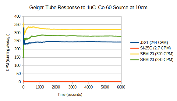
Measurements onverging to Steady Values with Time
Based on this, I allowed for a settling time of one hour for the rest of my measurements. There is definitely some error in exact distance from the source, but this should give a general idea of sensitivity:
| Tube | Background CPM | 0.91 uCi CPM | Delta CPM |
CPM per mR/h |
|---|---|---|---|---|
| SBM-20 (sample a) |
17.6 | 319.2 | 302 | 2516 |
| SBM-20 (sample b) | 16.1 | 279.3 | 263 | 2191 |
| M4011 | 243.7 | 15.7 | 228 | 1900 |
| SI-25G | 0.18 | 2.71 | 2.53 | 21 |
| SI-3BG | 0.15 | 1.84 | 1.69 | 14 |
The sensitivity value in the SBM-20 datasheet is 22 CPS/mR/h which comes out to 1320 CPM/mR/h which is a bit less than twice the sensitivity I measured here. A factor of two isn't going to get you killed, but definitely think of any surplus tube as a "for indication only" tool.
Utility of High Rate Tubes
The SI-25G and SI-3BG tubes are not very sensitive. One of the main reasons I bought a source was to see if these tubes worked at all. These tubes are not useful for detecting small amounts of radiation, but they are useful for detecting high rates of radiation. In particular, they would be useful for reassuring people in the aftermath of a nuclear attack that radiation levels are acceptable. Here is a passage from "On Thermonuclear War" by Herman Kahn (one of several influences for Kubrick's Dr. Strangelove in the eponymous film) which is a book of lectures on the topic of a nation preventing and responding to a nuclear conflict:
Probably the most important special equipment that would be needed—and the least improvisable—would be radiation meters of various kinds. These are not only useful during and immediately after the attack; they are necessary for many basic and important postwar activities. Meters could play an essential role in maintaining the morale and the risk-taking capacity of the cadres who would be exposed to radiation. It is easy to see why this is so. The radiation from fallout has curious and frightening effects. Most people already know, or will know in a postattack world, that if you get a fatal dose of radiation the sequence of events is about like this: first you become nauseated, then sick; you seem to recover; then in two or three weeks you really get sick and die. Now just imagine yourself in the postwar situation. Everybody will have been subjected to extremes of anxiety, unfamiliar environment, strange foods, minimum toilet facilities, inadequate shelters, and the like. Under these conditions some high percentage of the population is going to become nauseated, and nausea is very catching. If one man vomits, everybody vomits. It would not be surprising if almost everybody vomits. Almost everyone is likely to think he has received too much radiation. Morale may be so affected that many survivors may refuse to participate in constructive activities, but would content themselves with sitting down and waiting to die—some may even become violent and destructive. However, the situation would be quite different if radiation meters were distributed. Assume now that a man gets sick from a cause other than radiation. Not believing this, his morale begins to drop. You look at his meter and say, "You have received only ten roentgens, why are you vomiting? Pull yourself together and get to work." This view is in accord with experience in peacetime disasters that have been complicated by epidemics. People often require some kind of talisman before they will expose themselves—a shot, a pill, a gauze bandage around the nostrils and mouth or, in this case, a meter. They need, of course, other equipment in addition to meters, but a meter may well be the most essential. In the RAND civil defense study we suggested the immediate purchase of about $100,000,000 worth of radiation meters, so that this nonimprovisable but vitally necessary piece of equipment will be available.— Herman Kahn, On Thermonuclear War
The onset dose for symptoms of acute radiation exposure is around 35 rad though many people will not experience symptoms even at 100 rad. The maximum working rate of an SBM-20 tube is, per the datasheet, 144 mR/h. At that rate, it would take weeks for someone to get to that level of dose. For assessing the risk of a brief activity in a post-attack environment, you either need high rate tubes or an ionization chamber. Assuming a similar recovery time to SBM-20, these high rate tubes should be able to handle operation at up to ~5 R/h — maybe the 3 Rontgen line from HBO's Chernobyl was in relation to a Geiger counter and not an ionization chamber.
At 5R/h, it will take 6 hours to begin to experience symptoms of acute radiation poisoning, so a high rate tube is far more appropriate for assessing risk in the immediate aftermath of a nuclear event. If the tube isn't overloaded (which you can determine by shielding it and seeing if the rate goes up or down), then you're going to be fine in your present environment for many hours.
Software
All three versions of this board enumerate as USB virtual serial ports, but since V2 and V3 can operate without a USB cable connected, I added support in software for bluetooth. It's crappy copy pasta of examples, and it doesn't work with iPhones (they have neutered support for classic Bluetooth if you don't pay them) but it works reasonably well for Android. This lets you see real numbers on your phone instead of just listening to clicks.
The name of the Geiger counter bluetooth device is "Geiger-12345" where 12345 is a somewhat unique sequence of five numbers taken from the base mac address of the esp32 chip. I use an Android app called "Serial Bluetooth Terminal" to interface with the Geiger counter.
The Arduino sketch can be on the Github project.
Radiation on Planes
Cosmic rays are a significant source of background radiation. High energy cosmic rays cause hadronic showers of secondary particles as they interact with the atmosphere. This results in increasing background radiation with decreasing altitude as these secondary particles cascade into yet more lower energy secondary particles. At around 20-30km altitude, more particles begin to be absorbed by the atmosphere than are created as secondaries, and background radiation begins to drop. Since not much beyond Lockheed U-2 aircraft fly above 20km, many references to radiation aloft will lead you to believe that radiation monotonically increases with altitude. For practical aircraft centric purposes, it does, but the physics behind why and the fact that there is a altitude of maximum radiation are worth considering

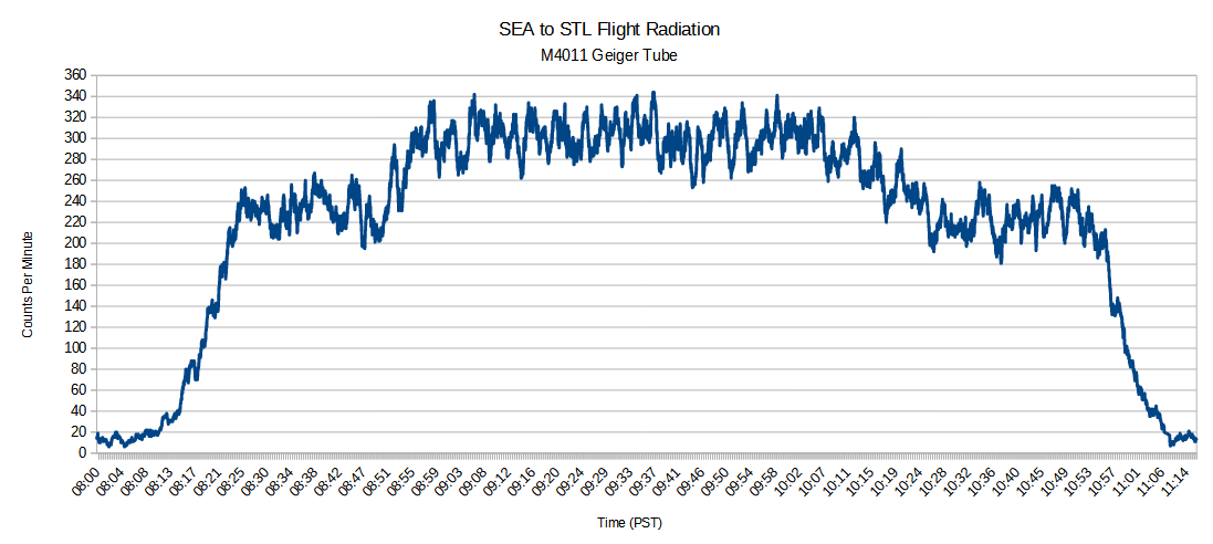
Background Radiation on a Commercial Flight
Anyway, radiation on a commercial flight will typically be 10-100x higher than radiation on the ground. The plot here was recorded by one of my Geiger Counters on a flight between St. Louis, MO and Seattle, WA using PuTTY to log the readings. I started recording after the plane had taken off, so the notable drop in rate toward the end is the plane descending into Seatac and landing.
Update December 2024
I used the "Serial Bluetooth Terminal" app on my phone to log the measurements from a flight from Seattle to St. Louis, and this time I caught both takeoff and landing:
Background Radiation on a Commercial Flight: Takeoff, Cruise, Landing
I also returned to the Mallinckrodt bike trail contamination site by walking across the McKinley bridge with my dad from the Illinois side, but it had unfortunately been mitigated to such an extent that the Geiger counter detected nothing above background.

Author Vainly Attempting to Detect WWII Era Radiological Contamination