Making Neutrons by Accident
2021
A significant confounding factor in radiation testing is the effect of radiation on support circuitry for the device under test. If you are testing an analog to digital converter and verifying its functionality using a microcontroller, then you must be careful to isolate radiation induced upsets in the microcontroller from radiation induced upsets in the DUT. One way that this can be done is with shielding: if the microcontroller receives no relevant radiation, then it can be assumed to not contribute to the measured upset rate.
The problem is that secondary particles — most problematically fast neutrons — are produced when the high energy protons are stopped using a heavy metal shield like lead. As it turns out, a lead shield with just enough thickness to fully stop protons is an efficient source of neutrons produced through nuclear spallation. Low density shielding materials like polyethylene on the other hand are able to stop protons without generating large numbers of spallation neutrons. The downside is that a much thicker shield is needed which can be unwieldy when area to be shielded is only a few square cm and the shield itself needs to be ~25cm thick.
What a Nikon D3200 Sees Behind a Lead Brick Exposed to ~3e8 200 MeV Protons/cm^2 — The Camera Became Unresponsive After this Shot and Remained So Until the Battery was Removed
Neutron Production
The production of neutrons from high energy charged particles is called spallation and it is only possible with high energy protons (unlikely to happen with protons <100MeV). Spallation is a complex process, so I will quote a helpful Los Alamos National Lab paper rather than trying to explain it myself:
What is spallation, anyway? - Spallation refers to nuclear reactions that occur when energetic subatomic particles (such as protons in an accelerator beam) interact with an atomic nucleus. [...] Spallation takes place in two stages. In the first stage where the proton interacts with the target, the incident particle creates a high-energy cascade inside the nucleus. High-energy (>20 MeV) "secondary” particles and low-energy (<20 MeV) “cascade" particles escape the nucleus, leaving the nucleus in a highly-excited state. In the second or evaporation phase, the excited nucleus relaxes, primarily by emitting low-energy “evaporation” neutrons. For heavier nuclei (such as lead), high-energy fission can also occur, competing with evaporation. For lead, the dominant mode of nuclear deexcitation is by evaporation rather than high-energy fission.— G. J. Russell et. al., Accelerator-Driven Targets: Understanding the Spallation Process
While spallation is an undesirable phenomena when trying to shield components on a circuit board from protons, it is useful in research settings as a controllable source of fast neutrons such as at facilities like the Los Alamos Neutron Science Center (LANSCE).
Illustration of Spallation Spallation Physics - An Overview
The yield (number of neutrons produced / number of protons impinging on the target) of these spallation reactions depends on target geometry and on the energy of the incident protons. Conventional spallation targets are designed to maximize leakage — that is, the number of neutrons leaving the target. Targets are designed with diameters large enough to allow for high energy secondary particles to contribute to the cascade prior to leaving the target. When spot shielding a large diameter proton beam, though, efficiency will be lower because some secondary particles will escape the sides of the shielding block before further contributing to the cascade.
Yield of Neutrons vs. Target Geometry
Assuming an efficient target, yield can be calculated from the atomic mass of the target and from the energy if the incident protons. From Physics and Technology of Spallation Neutron Sources equation 2.6, that is:
Where 'a' is 0.1 for all heavy elements, 'b' is 0.12 GeV (an effective threshold energy), and 'A' is atomic mass. For lead in a 200 MeV beam, this becomes:
As noted before, a small shielding block is not an efficient target, so the actual yield of a shielding block in a large diameter 200MeV proton beam will be something less than this. One last note: angular distribution of spallation neutrons is isotropic at low energy levels, but the highest energy neutrons tend to exit out the back of the target, so highest energy particles created by the shield end up hitting the very thing that the shield is there to protect.
Spallation Neutron Angular Distribution vs. Energy for 2GeV Protons
Stopping Protons
Protons are charged particles which lose energy as they pass through through matter. The amount of energy that they transfer to their surroundings per unit length is inversely proportional to their energy. That means that as a charged particle slows down, it transfers more and more energy per unit length until it is fully stopped. A 10 MeV proton will be stopped in ~0.3mm of lead while a 100MeV proton will make it 15mm — a 50x difference in stopping length with a 10x increase in energy.

Bragg Curve of 200MeV Protons in Lead
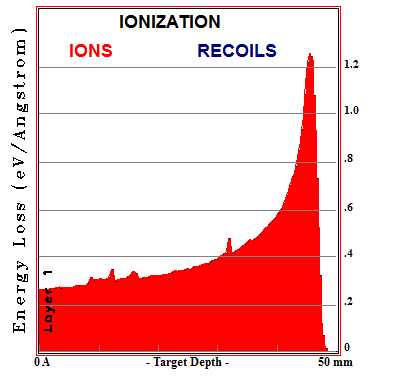
A plot of the energy loss per unit length vs. target depth is called a Bragg curve and the peak where a particle deposits the most energy per unit length is called a Bragg peak. This peak is exploited in proton cancer therapy to deposit energy inside a tumor deep inside the body while depositing less energy within the surrounding healthy tissue. By setting up multiple shots at different angles, the ratio between energy deposited in healthy tissue to energy deposited in cancer tissue can be further increased.

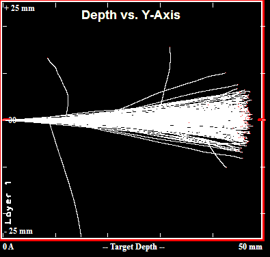
Simulated Paths of 200 200MeV Protons in Lead
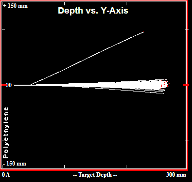
A free simulation tool from the 1990s called TRIM (Transport of Ions in Matter) can be used to calculate shielding thicknesses required to fully stop charged particles in various materials. As shown above, the tool predicts that 50mm of lead is sufficient to stop 200MeV protons, and as shown below that number is ~245mm for polyethylene.

Simulated Paths of 200 200MeV Protons in Polyethylene
Stopping Neutrons
Stopping fast neutrons is tricky. First you must moderate the neutrons, then you must absorb the neutrons, then (if you are protecting people) you must absorb the gammas generated when the neutrons are absorbed. This is why massive concrete labyrinths are needed to shield beam lines from areas occupied by people.
Boron-10 Neutron Absorption Cross-Section
Those familiar with the Chernobyl disaster may know that boron is good at absorbing neutrons. The propensity of an atom to interact with a neutron is known as its neutron cross-section, and it is expressed in barns which are a unit of area equal to 10^-24 square centimeters. This humorously named unit comes from WW2 work on the Manhattan project where the aim was to obscure its meaning. Borated polyethylene with a few percent boron-10 is used as a lightweight shielding material for Boron does in fact have a very high absorption cross section for thermal neutrons (neutrons that have been moderated in a room temperature moderator and which have a typical energy of 0.025 eV), but boron-10 is about 10,000 times less effective at absorbing 1 MeV (σ=0.3 b) neutrons as compared to thermal neutrons (σ=3844 b). This is why neutrons must first be moderated (experience numerous elastic collisions with light nuclei like hydrogen) prior to being absorbed. Concrete with added boron is good for shielding rooms because it contains a large amount of water (which contains a large amount of hydrogen).
Boron-10 Neutron Scattering Cross-Section
The neutron scattering cross-section of boron-10 at 1MeV is around 2 b, but the neutron scattering cross-section of protium (hydrogen-1) at that energy is 4 b. Natural boron is only 20% boron-10, though. The remainder is boron-11. The fast neutron cross-sections of B-10 and B-11 at 1MeV are similar which is all that matters for this example, but its worth pointing out that the absorption cross-section of thermal neutrons in natural boron is only around 20% of 3844 b since the contribution of B-11 is comparatively negligible.
Protium Neutron Scattering Cross-Section
The number of atoms per volume along with the microscopic cross-section determines the macroscopic cross-section. Polyethylene contains around 0.14 mol H per cm^3 while sodium tetraborate (borax) contains 0.018 mol of B per cm^3. There are five times as many hydrogen atoms per hydrated molecule of borax as there are boron atoms, so that comes out to 0.09 mol of H per cm^3. Since the scattering cross-section of hydrogen is about twice that of boron at 1 MeV and there are five times as many hydrogen atoms per mol borax as boron atoms, the hydrogen atoms in borax scatters ten times as many 1 MeV neutrons as the boron atoms. Again, boron is great at absorbing thermal neutrons, but nothing special for absorbing fast neutrons.
Boxes of laundry grade borax are sometimes used in radiation effects testing in an attempt to shield test equipment against neutrons, but as the previous example shows, borax is not particularly more effective than common polyethylene when you're trying to shield against fast neutrons. In my personal opinion, you're much better off limiting the production of neutrons to begin with by using polyethylene as a shielding material where practical.

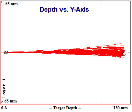
Simulated paths of 100 200MeV Protons in Aluminum
Aluminum should, per the spallation yield equation shown previously, produce (207+20)/(17+20)=6 times fewer spallation neutrons than lead. 13cm of aluminum is sufficient to stop 200 MeV protons. While 13 cm is more than twice the 5 cm of lead needed to do the same, it is better than having to deal with 25 cm of polyethylene.