70CM Filter
2024
I built a pager (yeah the ones from the '90s) transmitter using an SX1262 based module and an ESP32, but I wanted more than the paltry +20dBm (100 mW) offered by the RFM98W-433S2 radio module that I was using. I decided to try out some cheap amplifiers off of eBay, but I wanted to be a responsible amateur radio operator and suppress the likely high harmonics of these amplifiers. There aren't any reasonable medium power (~5W) low pass filters on the market for this sort of application, so I decided to make my own.
Two 70CM Filters
Design
I am writing this a year after the fact, so I don't have the original simulations handy. I used QUCS (since I hadn't discovered QucsStudio at that time) to generate a 5th order T-Type Chebyshev low pass filter. The pagers (Apollo AL-A26 Pilot) I designed the transmitter to support can be hand programmed down into the 70CM band, but they do not support the entire 70CM band. I settled on 449.95MHz. This isn't exactly compliant with the 70CM band plan, but I only use these in the middle of nowhere.
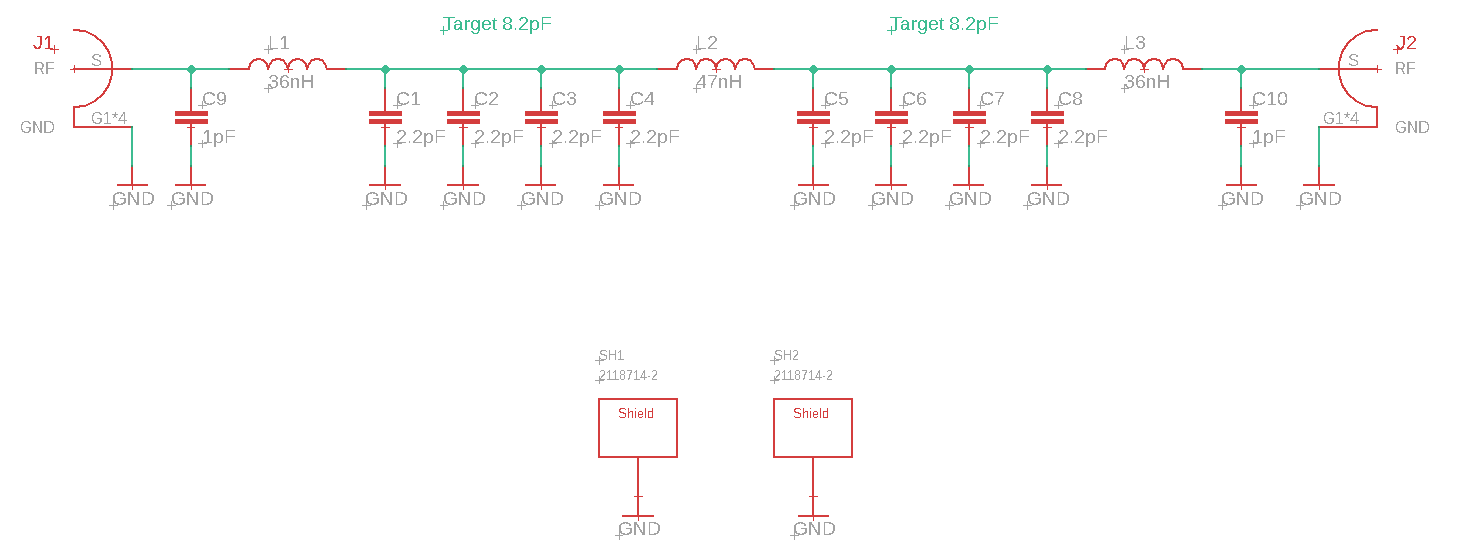
70CM Low Pass Filter Schematic
I designed for something like a 1dB passband ripple and then tweaked the ideal values to values that I could actually buy. With these sort of filters, it is normally easiest to select an available inductor value and then a capacitor value since precision capacitors are available with higher granularity in values. Here, I placed a few capacitors in parallel for even more flexibility. You can tune the filter without changing the inductor — at the expense of maintaining the designed passband ripple — by changing the capacitance which is exactly what I did here. A filter designed for a fixed frequency transmitter (such as this) can be optimized further than a filter for a transmitter that can tune over the while band. Specifically, you can tune filter to have minimal loss at the fixed transmit frequency at the expense of wideband performance. This allows you to have more passband ripple with effectively no consequence allowing for a faster rolloff for a given filter order. I have seen this referred to as "peak tuning" since a peak in the S21 (forward gain which will always be less than unity for a passive device) of the filter.
For the inductors, I chose Coilcraft 1111SQ series inductors which have "exceptionally high Q." These are just air core inductors — coiled pieces of wire. I could coil my own pieces of wire and achieve equivalent performance, but I like to reduce the number of variables when possible when working with custom designs.
Construction
I opted for a 2-layer PCB with through hole SMA connectors. I didn't simulate or iterate on transition designs, but I did a decent job of guessing. I calculated the impedance of a coaxial cable with the dimensions of the transition and adjusted the ground plane setback to meet that which ended up being to the pads of the ground pins.
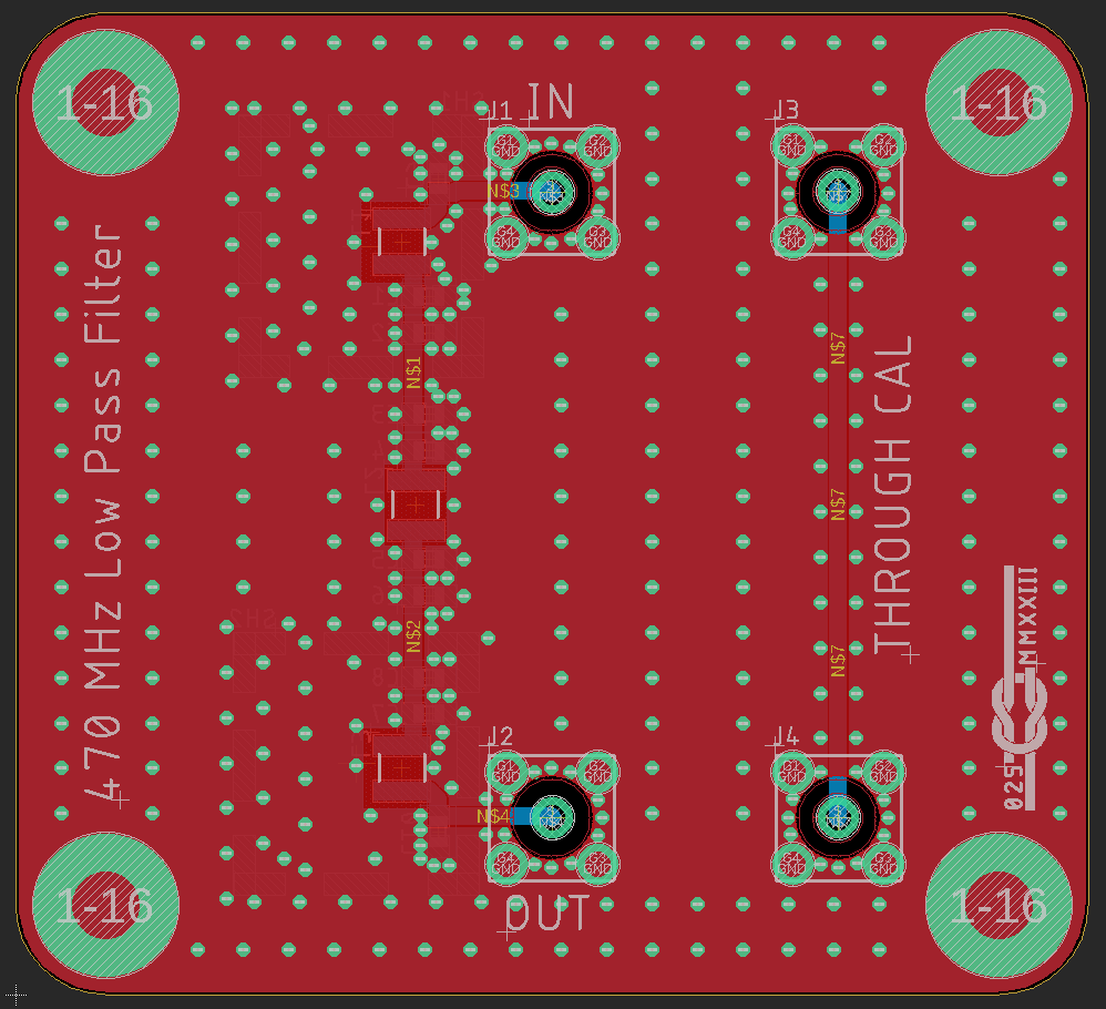
Filter PCB Layout Showing Through Hole SMA Transition
I suspected that I may need to shield the filter sections to avoid unintentional coupling, so included the footprint for a 2118714-2 RF shield can frame. Overall, the filter is housed inside of a Hammond 1550Q enclosure with the PCB screwed to the box as a lid with the filter sections inside. I like Hammond boxes, but this one, annoyingly, uses M3.5-0.6 screws rather than Imperial 6-32.

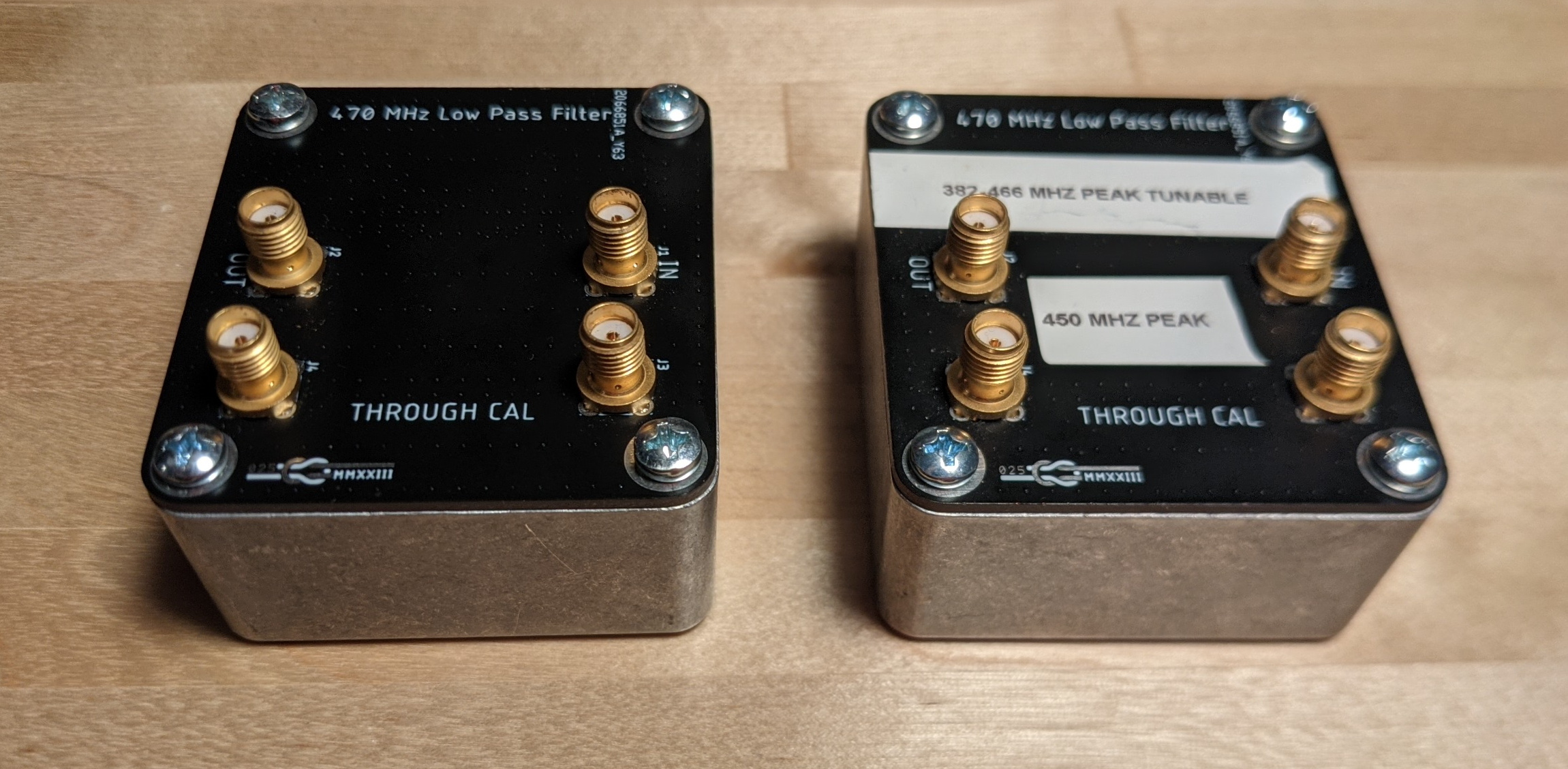
Left: Adjustable Filter, Right: Fixed Value Filter with Shield Cans
The process of determining the ideal capacitor values for my peak frequency is iterative and annoying. I realized after wasting an hour soldering capacitor kit values that I could solder in ~2pF less than the ideal capacitance as fixed capacitors and add in parallel a 1.5-3pF JZ030 variable capacitor that I had in my parts box that I bought for an RF project a couple years ago. There wasn't a footprint for these on the board, but I just scratched off the soldermask with a #10 blade scalpel and made it work.
Power Handling
Results
I tuned the adjustable filter to a peak frequency of 450 MHz to match my pager transmitter, and the fixed value filter ended up at 432MHz.
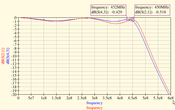
S21 = Adjustable Filter Insertion Loss, S43 = Fixed Filter Insertion Loss
My fears of higher frequency coupling in absense of shielding the filter sections from each other were realized, but not to an actually relevant extent. There is some mode inside the box that causes coupling at higher frequencies, but the magnitude of the coupling is low enough that it is inconsequential.
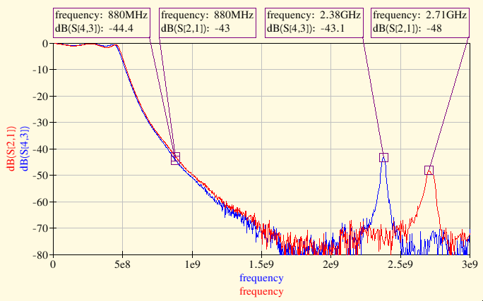
S21 = Adjustable Filter Insertion Loss, S43 = Fixed Filter Insertion Loss
The end product worked quite well for my application: ~0.5dB attenuation and greater than 40dB attenuation of the second harmonic. Of that 0.5dB, most of it ia from the filter components and not from the SMA transitions and transmission lines. The through measurement trace shows that the SMA transitions are rather good (<-25 dB S11) and that the through loss is only 0.03dB.

Through Measurement Trace
I made these measurements with a NanoVNA controlled from my desktop using NanoVNA-Saver:

Measurement Setup