DNVT Physical Interface
2023
DNVTs communicate through transformer coupled differential pairs. Each phone has a receive pair and a transmit pair and is powered through these data lines when the phone is connected to a switch in CB (Common Battery) mode. The DNVT RCV is the positive supply and the XMT pair is the negative supply. To emulate this interface, you need a center-tapped transformer that will not saturate at the frequencies used by DNVTs and a differential transceiver that can produce line levels appropriate for DNVTs. While the line code (differential manchester) is part of the physical layer interface in the OSI model, I've covered that on my DNVT Control page.
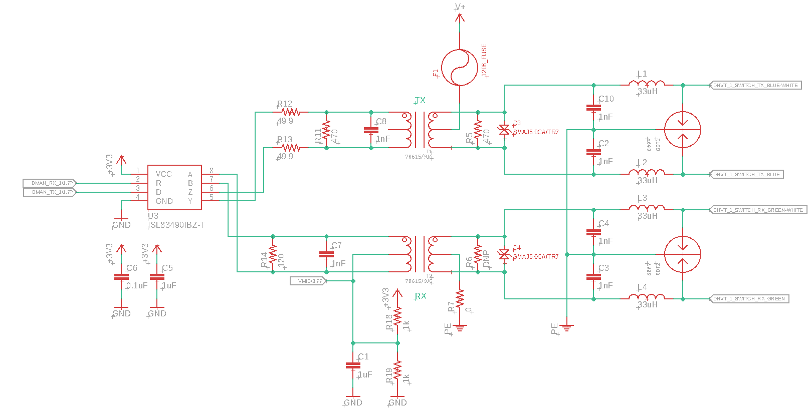
Line Interface Section of DNVT Switch Schematic
The physical layer for DNVTs is similar to 10BASE-T ethernet; both use transformer isolated differential signals with a variant of Manchester encoding, and both can power remote devices through the center-taps of their isolation transformers. You cannot use Ethernet transformers for DNVTs, though, because the frequency content of a DNVT signal starts at 16 kHz while a 10BASE-T transformer only needs to pass frequencies stating at 10 MHz.
Hardware
Transformer Selection
When operated at 16 kbps, the longest the line can be high or low is 1/16k=62.5 µs. At 32kbps, it is 31.25 µs. While the RS-422 driver outputs +/- 3.3V, the transformer is after resistors that drop that voltage further. With a long cable (highest supported line resistance) the voltage at the input of a transformer on the transmitting side simulates as +/-1.7V with my driver circuit. Pulse transformers are rated in volt-second products, so, for 32 kHz, the volt-second product needs to be greater than 53 Vµs.
I initially thought that it would be fun to hand-wind toroidal transformers to interface with the phones. I quickly remembered how much it sucks to hand wind transformers. Instead, I searched Digi-key for the highest magnetizing inductance 1:1 center-tapped pulse transformer and found a 10 mH 56 volt-microsecond transformer that looked like it fit the bill. At $1.50, this sure beat winding a toroid by hand. Inside the package, you will find a small potted toroid.
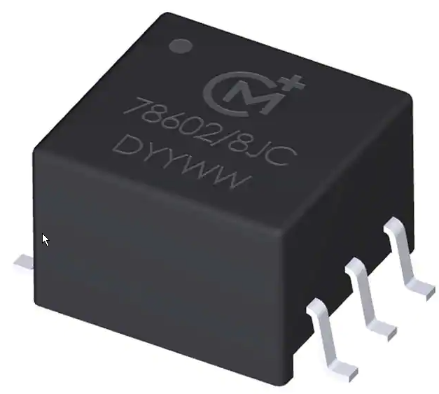
Murata 78615/9JC 10mH 1:1 Center-tapped Transformer
Note that, while this transformer meets the volt-microsecond product for 32 kHz operation, it does not meet the Vµs product for 16 kHz operation. I would have gone with a higher volt-microsecond transformer had one been available; nonetheless, the transformer does work at 16 kHz without appreciable distortion though I have not tested this over temperature.
Driver and Receiver
I found that DNVTs use discrete transistors to drive their TX signal and a general purpose comparator for differential reception when I tore down a phone. Since it is no longer 1980 and proper RS-422 differential transceivers can be found pretty cheaply, I opted to use those rather than directly copying the circuit in the DNVTs. RS-422 defines an electrical interface, not the specific signaling running on it. It is commonly used to encode Asynchronous serial, but you can transmit whatever digital signal you'd like using these transceivers. Asynchronous serial does not preserve a DC balance (equal time spent digital high and low), so it cannot be transformer isolated (the transformer would saturate). There is nothing stopping you from transformer isolating a DC balanced signal (such as Manchester encoded DNVT data) generated by an RS-422 transceiver, however.
Transformers are not 'ideal'. The core, as previously mentioned, will saturate if too much flux builds up. Beyond that, the primary and secondary windings are not perfectly coupled. This imperfect coupling results in a parasitic 'leakage' inductance which can be simply modeled as an external inductor in series with the primary winding. When the drive signal to the transformer flips, the energy stored in this parasitic inductance must be dissipated. I expected to need to do something to dissipate this energy, so I added series and parallel elements between the transceiver and transformer to provide options for mitigating it.
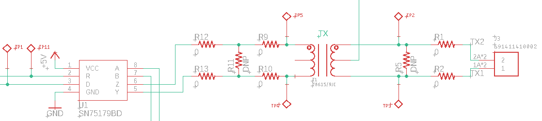
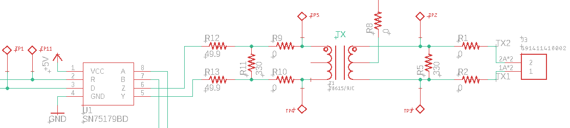
Initial TX Circuit with Placeholder Termination Parts
I initially used a SN75179 RS-422 transceiver (when I was initially testing with an STM32 as described below). When the driver of this transceiver was directly connected to the transformer, I observed voltage spikes that violated the absolute maximum ratings of the part (-10 to +15V).
Large Voltage Spikes from Driver Directly Connected to Transformer
The driver output includes series diodes which block the inductive spikes from being dissipated into ground and the supply of the device. Also, the differential amplitude of the TX signal after the transformer was greater than that produced by a DNVT.
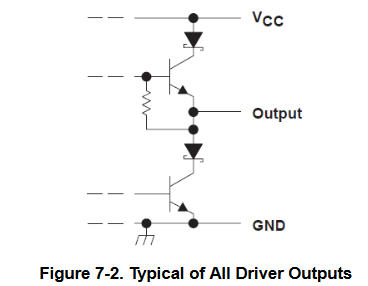
SN75179 Output Equivalent Circuit
To tackle both problems at once, I added series and parallel resistors to drop the amplitude and to snub the voltage spikes. I played guess and check with the values until I arrived at the circuit below. In the final version of the switch (schematic shown at the top of this page), I added parallel 1nF capacitors to reduce the ringing frequency of the spikes and increased the value of the damping resistors across primary and secondary to 470Ω to better match the 120Ω that the phones were designed for.
Modified TX Circuit
There are still spikes with the added damping, but they are now well within the limits of the driver. The spikes are higher in amplitude at the transformer than they are at the driver itself due to the 49.9 Ω series resistors. After these changes, the output of the switch as quite clean.
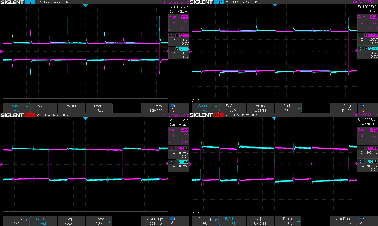
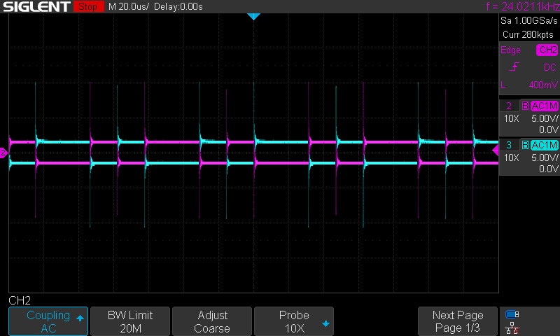
Top Left: TX Transformer Input, Top Right: Driver Output, Bottom Left: TX Transformer Output, Bottom Right: RX Transformer Input
No extra circuitry was needed on the receive side as can be seen above: a single 100 (or 125) Ω termination resistor is sufficient.
Protection
Line Protection
Since these phones are designed for use with long cables running outside, they include significant transient voltage protection. While I would not expect them to survive a direct lightning strike, they should be able to handle significant surges from indirect strikes without damage. For the switch, I just copied the protection circuit from the DNVTs since I don't have any plans for permanent installations with multiple km of outdoor wire and have no plans to perform any formal qualification testing. This part of the switch PCBA is nice to look at at least.
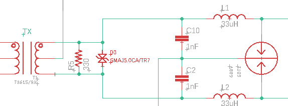
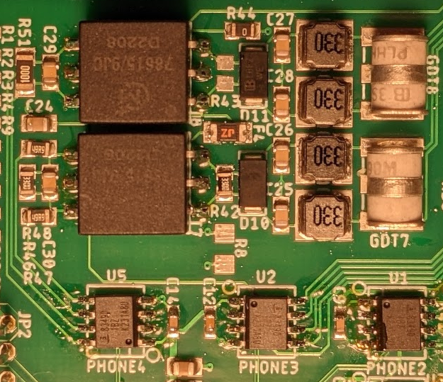
Input Protection Circuity
The protection circuit has two stages. The first is a three-pole gas discharge tube (GDT) connected directly across each pair. Gas discharge tubes nominally present as an open circuit (only a handful of pF to the signal lines) and become a short circuit capable of handling 1,000+ Amps when their spark-over voltage is exceeded. There are two limitations of GDTs in circuits like this: First, they take a finite amount of time to fire trigger, and before they trigger the voltage on the lines can greatly exceed the nominal trigger voltage. Second, they can cause partial common mode to differential mode conversion of surges because both sides of the tube do not arc over simultaneously. Transformers are inherently good at handling common mode surges — if the same amplitude surge is applied to both sides of the primary winding, the only energy that is coupled to the secondary is through the inter-winding capacitance. When a three-pole GDT fires, one side may be very slightly delayed with respect to the other resulting in a brief differential mode signal appearing on the transformer which will couple through to the secondary side.
Line Interface Section of DNVT Switch
I am not sure what the voltage rating of the GDT used in the DNVTs is. On the first revision of the switch, I used a 90V GDT from "Brightking" which, conveniently, has an identical footprint to more reputable Bourns part but at 1/6 the price. On the second revision, I changed to a 470V rated part since both the transformer and power supply blocking diode can easily handle such voltages. The stand-off voltage of the 90V rated part was only 50V which was a bit low since the phones are happy to accept nominal supply voltages up to 56V.
To overcome the limitations of GDTs, the DNVTs have a second stage of protection. There are 33uH inductors between the stages which serve to divert energy into the GDT by blocking sudden voltage spikes. After these inductors, a bidirectional TVS (Transient Voltage Suppression) diode (I chose SMAJ5.0CA/TR7) absorbs differential voltage spikes above 6.4V. This small part is rated to a peak power of 400W at 9.2V which is within the -8/+12.5V absolute maximum rating of the RS-422 transceiver. One other layer of protection (often relied on with Ethernet) is that the maximum energy that can be coupled through the transformer into the transceiver for any transient pulse is limited by transformer saturation.
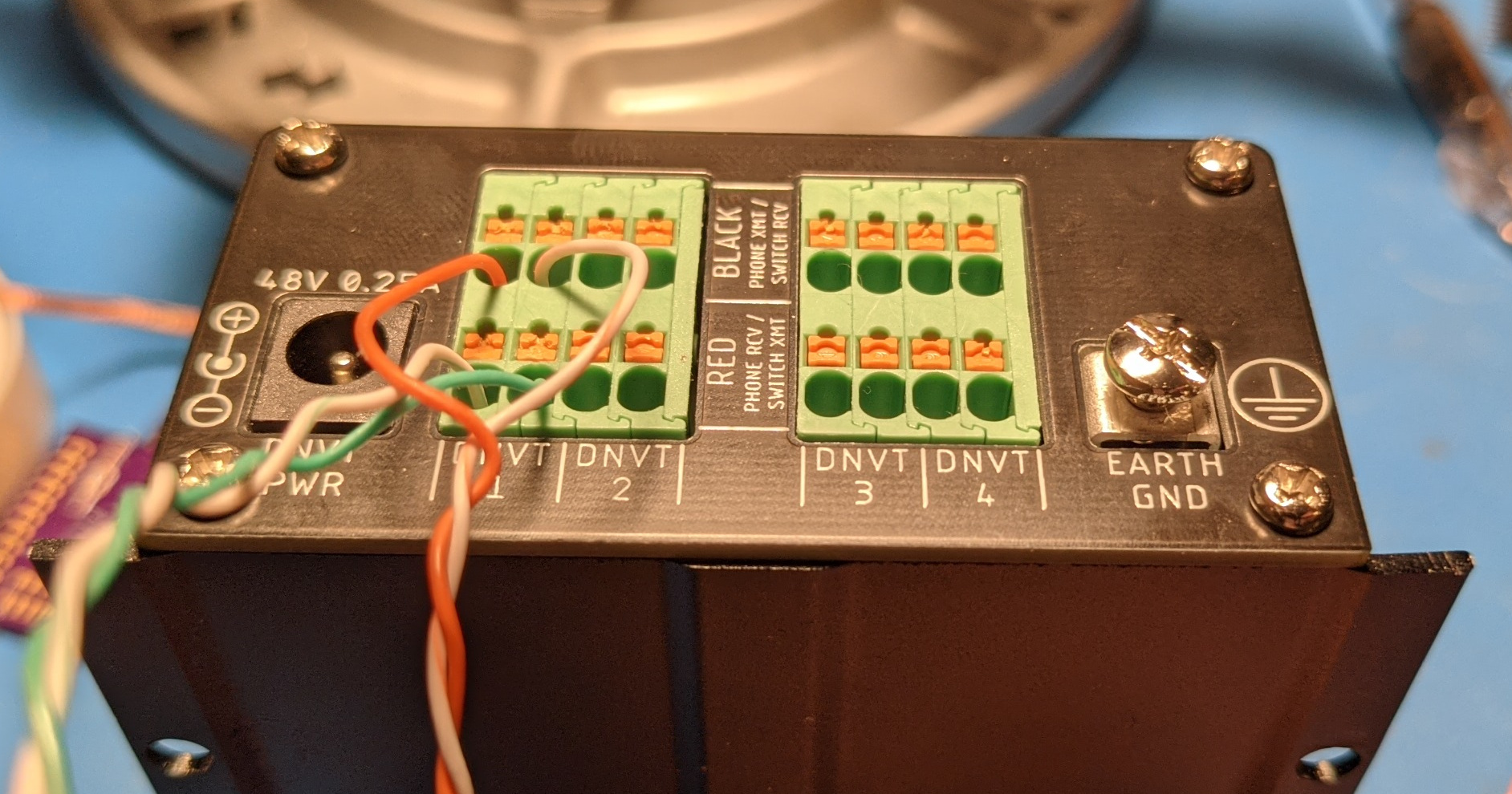
Earth Ground Lug on Custom Switch
Serious transient suppression parts like GDTs are only effective when used with appropriate grounding — where else would the energy go? Into the 48V power supply? I included a right angle screw terminal on the back of the switch to be connected into a protective earth ground to provide a low resistance ground path. These transient protection parts are only designed to protect the switch. Lightning transients can and will still travel from an outside line into the structure that the switch is located in unless there are additional protections added at the point of entry. Grounding is a surprisingly complex topic.
National Electrical Code (NFPA 70) article 800 governs the entrance of telecommunications cables to structures. Broadly, it requires that you either ground the shield of a cable at the point of entry, or (for unshielded cables) that the cable pass through a grounded protection device before entering a building. A certified PoE capable ethernet protection device would be an example of a protection device capable of protecting DNVT lines. They typically employ TVS diodes and GDTs that should have no issue with the DNVT signal. Note that this protection device must be grounded in accordance with article 800. There are a few options, but they all involve the protection device being placed outside the structure and that the protection device connect to the main grounding rod of the building. Phone, cable, and building AC power must either be connected to the same ground rod. In the case that the telecom entry points are far from the power entry point, it is acceptable to connect them to a secondary ground rod provided that the second ground rod is properly bonded to the primary ground rod.
That said, this is a hobby project. Do not recommend that the switch be used for any permanent installations or for critical communications. The switch is designed for temporary setups just for fun. Do not rely on it for life or death communications, and seek out expert advice if you intend to connect the switch to line exiting a structure.
48V Protection
The lines from the switch to the DNVTs are energized by a common 48V input, so short circuit faults on one phone need to be isolated from the other phones. I did this with resettable polyfuses. These parts present a low resistance (3.6-50Ω) before they trip and a high (and quite non-linear) resistance after they trip. The pass element in these devices is a polymer that melts when it gets too hot (either from self-heating or from being in a hot environment). When the polymer melts, its resistance greatly increases and stays melted with a 'hold' current (much lower than the initial trip current) until the load is removed. These worked out quite well — I can short out any of the lines and the 48V wall wart continues to power the remaining phones without issue. It helps that the resistance of the transformer limits the maximum current though the polyfuse prior to tripping as well.
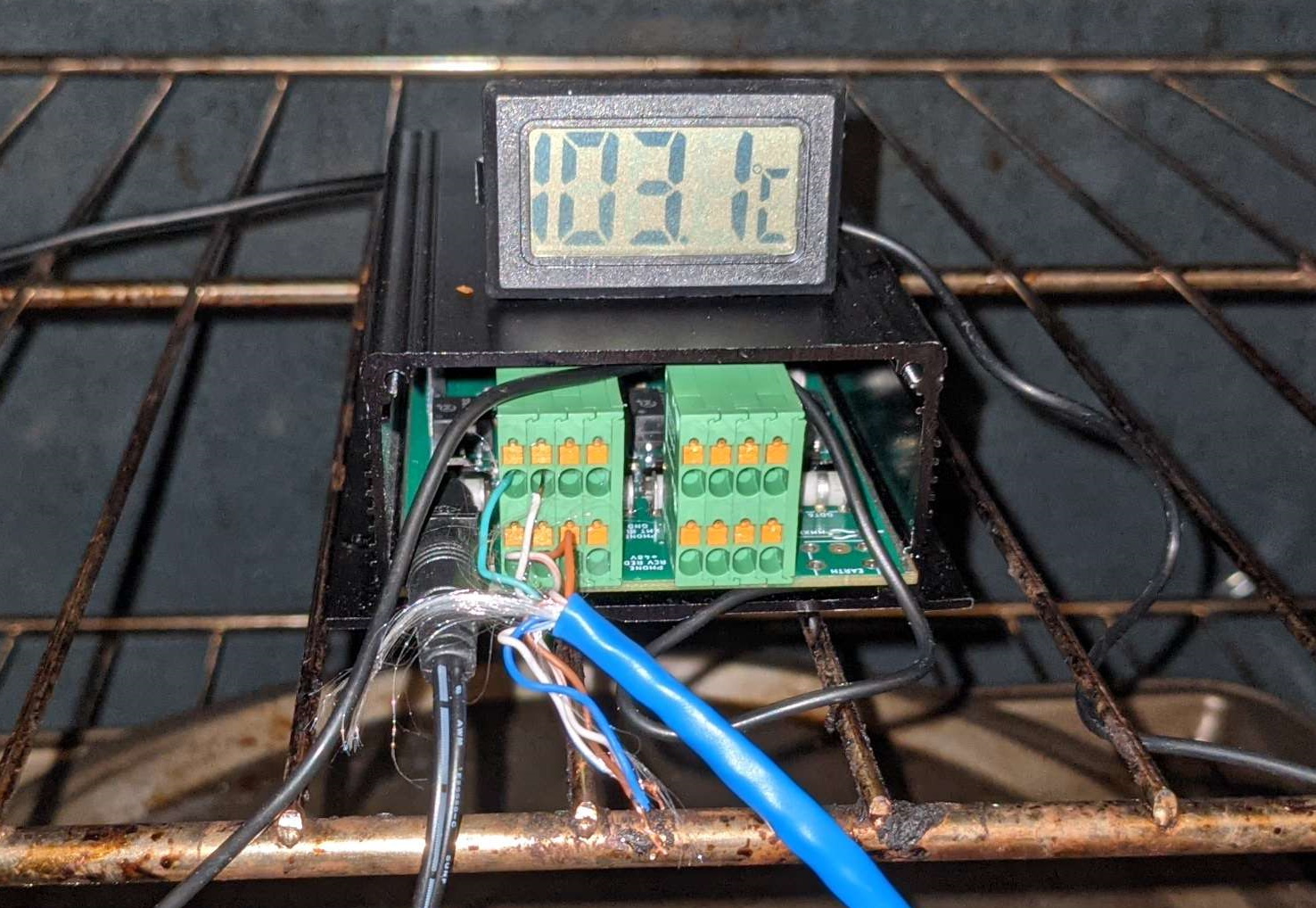
Environmental Testing in Oven
After seeing how well the polyfuses worked without even getting that noticeably hot when tripped, I was worried that they may be too sensitive for this application if the switch were, prior to tripping, hot. To see if this was a valid concern, I connected a temperature sensor to the bottom of the board under the polyfuse and put the switch in my oven connected to a DNVT through 4000' of crap cable. It worked fine until 90C board temp (it triggers during calls at 95C), so there should be no risk of triggering at normal temperatures. I also tested the switch in my freezer just for fun and saw no issues at -20C either.
I was worried that a surge from the lines could couple into the 48V supply, so I added a 1000V rated series diode followed by a small capacitor in line with the 48V input. It occurred to me while writing this that the circuit is not protected against negative transients, so I added a diode from ground to the 48V input to the final version of the switch. The switch is designed for use with limited power sources (power sources capable of supplying no more than 100W). If you want to connect the DNVT to a 48V battery, you should add an in-line fuse.
Range
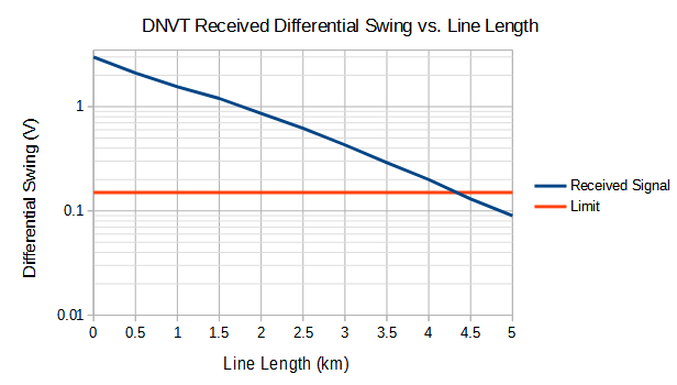
As with Power over Ethernet, there are two range limits for DNVTs: voltage drop and signal attenuation. Voltage drop depends on line resistance and phone power while signal attenuation depends on the transmission line characteristics of the wire. For 24 AWG copper twisted pair, the practical range is limited to about 4.5 km which is in line with the IEEE Paper which specifies a range of 4 km with "WF-16 Field Wire" which is constructed from a copper-cadmium alloy of unspecified resistivity.
Voltage Drop
These phones are specified to consume 1.5W, but in practice — at least at room temperature — I have found they consume a lot less. The same principle encountered with RF circuits where maximum power is delivered to a load when the load impedance matches the source impedance can be applied to the phones to determine the maximum loop resistance they can support. When you match your load and source impedance, you will see half of the source voltage at the load. With a 48V supply, you would then see 24V at the phones. At 24V, the phone will draw 1.5W/24V = 62.5mA. The resistance corresponding to a 24V voltage drop with this current is 24V/62.5mA = 384Ω.
As a side note, you can neither model the phones as a resistance nor as a constant current source over varying voltage because the phones use switched mode power supplies and, therefore, exhibit negative resistance: they consume more current as the applied voltage decreases because they need to support the constant power load of their electronics. At 48V, the phone would draw only 31.25mA. This assumes constant efficiency which, while not actually the case, is fine for the purposes of this analysis since we are starting from a, presumably, worst-case power number.
The power loop resistance to a phone is the resistance of the two XMT lines in parallel combined in series with the two RCV lines in parallel. Since all of these lines will have roughly the same resistance, the loop resistance is equal to R|R+R|R where R is the resistance of a single wire. Since the series and parallel combination R|R=R/2 and R/2+R/2=R, the power loop resistance is equal to the resistance of a single wire from the phone to the switch. Standard CAT-5e cable is composed of 24 AWG copper wire which has a resistance of 84Ω/km. With a resistance budget of 384Ω, the maximum range of the phones over CAT-5e is 4.6 km. Note that while the 'power' loop resistance is equal to that of a single wire the length of the line, the 'signal' loop resistance is twice that of a single wire the length of the line because the wires in the TX and RX loops are in series rather than in parallel like they are for power.
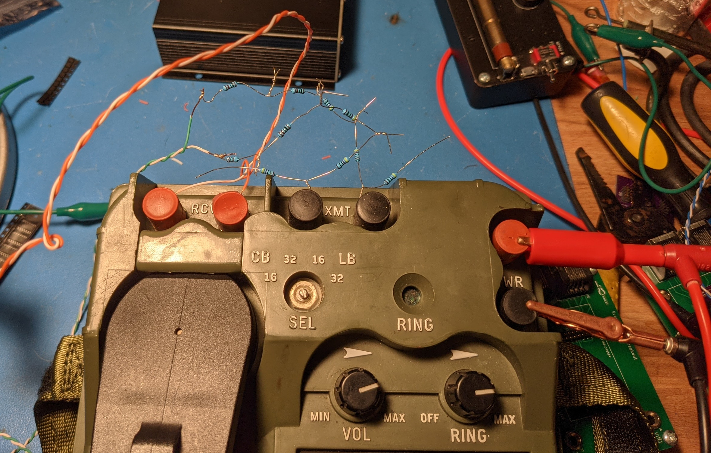
Line Resistance Testing
I was able to add 1 kΩ of power loop resistance (one 2k resistor on each of the two XMT or RCV lines) and the phones still worked (able to power up and receive / transmit data). The voltage drop across one of the resistors was 10.3 V which comes out to 5.2 mA. With 48-2*10.3=27.4V across the phone, this corresponds to a load of 0.14 W which is quite a bit less than the specified 1.5 W.
Signal Attenuation
The received signal needs to exceed the hysteresis of the differential receiver in order to be received. Cross-talk and noise from external sources will also impact the signal, but I'll keep things simple here and assume a quiet environment. The ISL83490 has a 50 mV hysteresis, and the phones are specified to have a minimum input level of 150mV, but there is some margin on that number as the test with 4kΩ signal loop resistance showed. In the absence of noise, these phones will work with input signals lower than the 150mV listed in the IEEE paper. The phone worked with 2k resistors on both RCV lines (4k signal loop resistance): this simulates to a swing of only 80mV at the RCV terminals. The phone stopped working with 2.47k on each line (~5k signal loop resistance). Regardless, I'll go with 150mV for these range calculations.
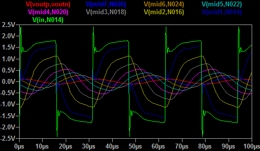
Simulated Attenuation through CAT-5e 24 AWG Copper Wire
The IEEE Paper states that: "Input levels fall between 150 mV and 4 V peak-to-peak; the output level is set at 3 V peak-to-peak." This appears to be the differential swing rather than the peak to peak voltage of either line in the pair. If one line has a peak-to-peak voltage of 1.5V (-0.75V to +0.75V) and the other line in the differential pair has the same waveform but inverted, then the differential voltage between them is -1.5V to +1.5V which is a differential swing of 3V. I bamboozled myself for quite awhile by looking at the peak-to-peak voltage of a single pair thinking that was the peak-to-peak voltage noted in the paper. Only after studying the waveform at the termination resistor of the switch and seeing that its peak-to-peak voltage was only 1.4V when the paper specifies 3V did I realize they were actually talking about the differential swing.
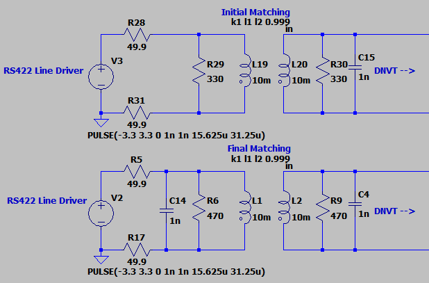
Switch Transmit Matching Changes to Better Match DNVT Transmit Amplitude in a 120Ω System
While CAT-5e cable is nominally 100Ω, these phones are specified for use with 120Ω field wire. I initially set my termination resistance at 100 Ω and set the drive voltage to match that of the phones terminated to 100Ω, but when writing this up I realized that I would get better performance (nominally longer range) if I increased the drive voltage and changed the termination resistance to 120Ω. The Scope captures in this section are from the 100Ω terminated system, but the calculations are for a 120 Ω terminated system which reflects what I actually used for the final version of the switch. The difference is pretty minimal — after 4km of CAT-5e, you will get 200 mV with 120 Ω termination and 183 mV with 100 Ω termination.
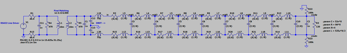
LTSPICE Range Simulation
I had a bit of back and forth with the range simulation. I initially simulated the line as a lumped element model: line resistance followed by a capacitor. I then broke the line into four segments, I got rather different results. Breaking the line into eight segments produced around the same result, so I stayed there for my simulations. I then added line inductance, and found a range higher than the original result. I then realized that I had bamboozled myself with a single-ended simulation and had included half the actual loop resistance, and then realized that I had misinterpreted differential swing for peak-to-peak voltage... After fixing all of that, I determined that you can maintain a >150mV received signal through 4km of CAT-5e cable.
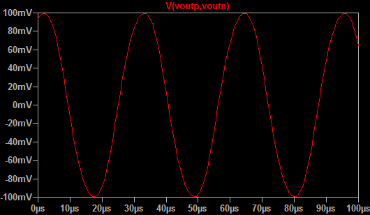
Simulated Differential Voltage After 4 km CAT-5e Cable
The reason that I saw better performance after adding inductance is that inductance helps you to satisfy the Heavyside condition. The first transatlantic telegraph line could only be run extremely slowly because it had insufficient inductance. Later lines were loaded with high permeability material to increase their inductance to allow for faster keying (higher bandwidth). CAT-5e cable has a loop resistance of 168 Ω/km, capacitance of 52 nF/km, and inductance of 525 µH/km. Longer analog phone lines used to have loading coils installed every 6,000 ft. to increase range at the expense of cutting off higher frequencies since these were lumped rather than distributed elements.
Simulated Differential Voltage at Various Points Along 4 km CAT-5e Cable
I did't have 4 km of CAT-5e cable laying around to test these simulations, so I bought a 1000' long spool of the cheapest "CAT-5e" cable on Amazon. This cable smells bad and uses brittle copper clad aluminum (CCA) rather than pure copper; I knew it was CCA before buying it, but I had no idea it would be this shitty. Pure aluminum is 66% as conductive as copper, so with 24 AWG copper having a resistance of ~26 Ω per thousand feet, I expected the resistance of this wire to be about 40 Ω. The actual resistance of a single 1000' wire was actually 65 Ω! The diameter of the wire is ~0.5mm which matches 24 AWG, so my best guess for why the resistance is so high is that the aluminum is not pure. With alloys, conductivity is not the sum of the parts. 7075 alloy aluminum is 89% aluminum, but its resistivity is 90% higher than pure aluminum. To speculate, I imagine that an alloy was used to make it easier to draw the wire, but I am no metallurgist. Let this be a warning: don't buy CCA "CAT-5e" cable. CAT-5e is in quotes because ANSI/TIA-568 defines the maximum loop resistance of CAT-5e as 188 Ω/km. This cable has a loop resistance of 426 Ω/km!
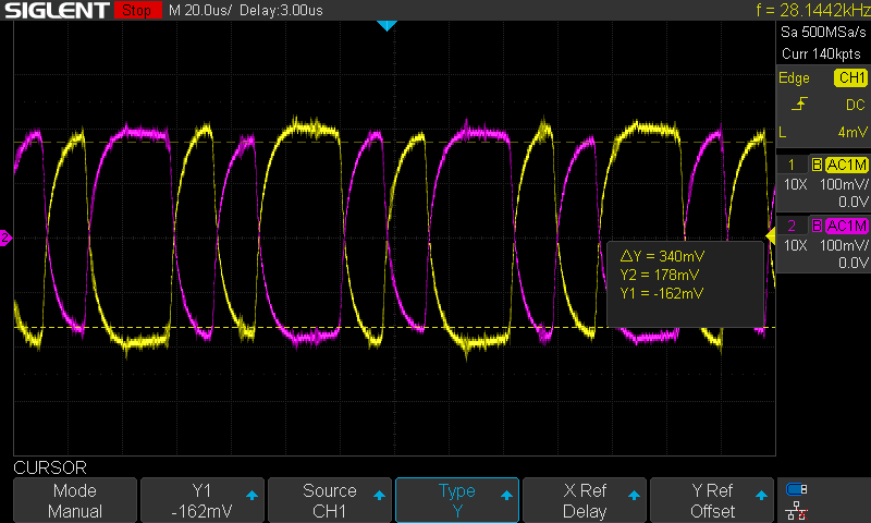
Measured Signal at Switch Receive Termination Resistor After 1.22 km of Aluminum "CAT-5e" Cable
Since there are four pairs in the cable, I connected all four in series to achieve a 4000' (1.22km) long test pair. I updated my simulation for the 213 Ω/km aluminum wire and set the distance to 1.22km, and the result quite closely matches what I actually measured: both show an approximately 680mV differential swing. 32 KHz transitions are the worst case for the circuit which is why I exclusively simulated 32 KHz. The actual line code, of course, also has 16KHz transitions, but they are equal to or greater than the 32 kHz transitions in amplitude. The difference is more pronounced with longer copper cables where cable capacitance attenuates the high frequency content more. Because most of the loss in this aluminum cable is resistive, the frequency dependance is less pronounced.
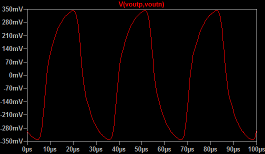
Simulated Differential Swing after 1.22 km of Aluminum "CAT-5e" Cable
Despite the signal looking pretty ugly after a long cable, the RS422 receiver does a good job of restoring the original signal.
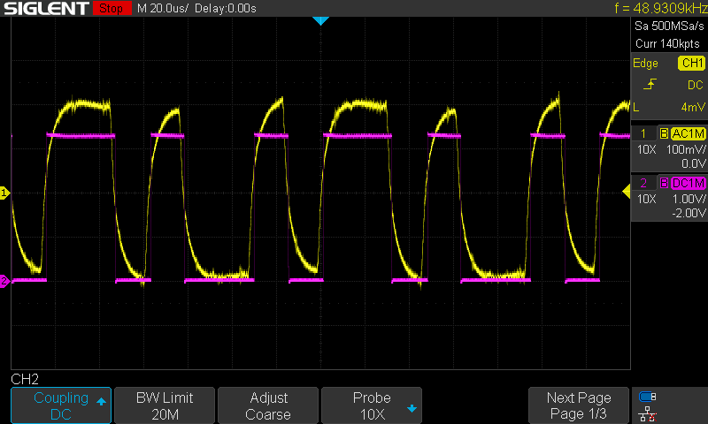
Decoded Signal After 1.22 km Aluminum "CAT-5e" Cable
The switch can handle higher attenuation than the DNVTs: The DNVTs stop functioning with 5 kΩ of signal loop resistance on their RCV line (while powered LB style since this is too much resistance to power the phones CB style) while the switch still functioned with 6 kΩ of signal loop resistance on the phone's XMT lines. Past this, the switch stopped receiving the phone as the differential swing was less than the 50 mV specified by the RS422 receiver.
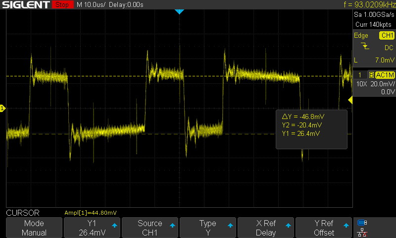
Signal at Switch Receive Termination Resistor with 6kΩ Signal Loop Resistance