Hardware Random Number Generator
2021
Rev1 SchematicRev1 Fabrication Outputs
Microcontroller Binary
Example Output
I've always liked the idea of one time pads. They are a simple and (as long as they are truly random) unbreakable encryption scheme. One great source of true randomness is radioactive decay. Geiger counters are what most people think of when they think about radiation detectors, but they require high voltage power supplies and can't detect alpha particles without expensive and fragile probes. Instead, I installed a photodiode with an exposed die in a transimpedance amplifier circuit and used that to detect alpha particles. Disclaimer: Do not try this at home unless you are educated on how to take appropriate safety precautions.
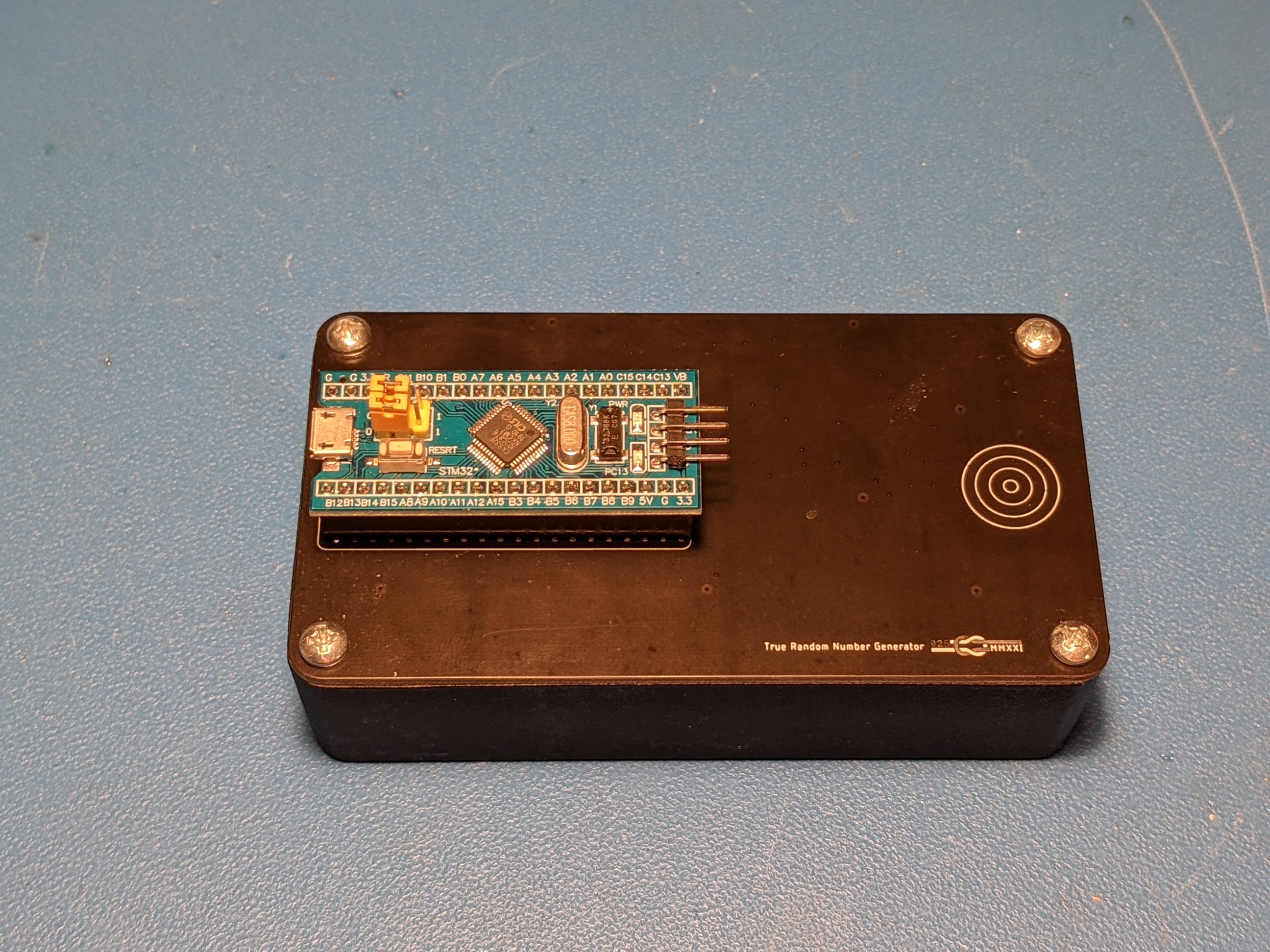
Final Box
To process the signal from the transimpedance amplifier circuit, I added a STM32F103 "Blue Pill" Development board to the top of the box. This outputs one time pads in the form of groups of five letters with five groups per line over a USB virtual serial port. Enabling the virtual serial port required actually programming the microcontroller using STM's IDE rather than the Arduino IDE that I have used with these boards in the past. This microcontroller can also be loaded with firmware to act as the data acquisition front end for a cell phone oscilloscope app called HScope, and I made sure to use the same ADC pins as that firmware expects. This allows the events to be seen in real time from a cell phone if that alternative firmware is loaded.
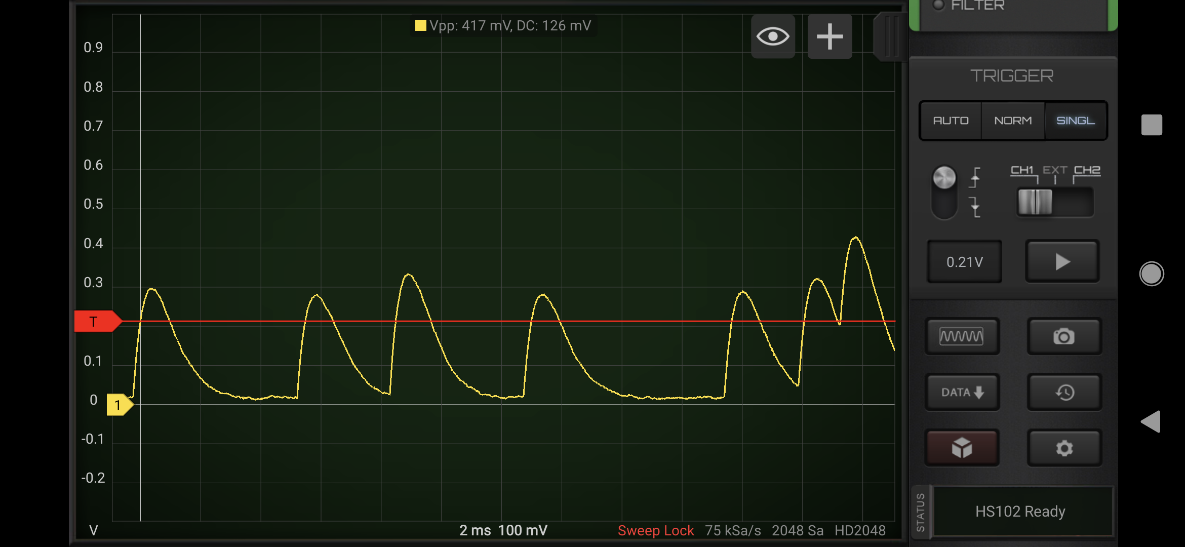
HScope Screen Capture Showing Alpha Particle Events
Theory
Alpha particles have high LET (Linear Energy Transfer) compared to gamma and beta radiation meaning that they deposit a large amount of energy per unit length as they pass through a material. In air, this means that alpha particles will create far more electron-ion pairs per unit length than beta or gamma radiation. When charged particles, including alpha particles, pass through silicon, electron hole pairs are created. If these electron hole pairs are generated in the depletion region of a PN diode, the electrons will flow toward the N-doped region (cathode) and the holes will flow toward the P-doped region (anode). The trick with detecting alpha particles this way is exposing the die so that alphas can actually make it to it.
The plastic packaging of typical photodiodes will stop alpha particles before they are anywhere near the active region on the die. Even a few cm of air will stop alpha particles, so the source needs to be right in front of the detector. This is why alpha spectroscopy is performed in a vacuum — otherwise energy lost to air would shift and spread the characteristic energy peaks.
There is a 1990's simulation package (with a 1990's era website) called SRIM (Stopping Range of Ions in Matter). It works great for calculating LET, energy lost after passing through a degrader, and distance required to stop a charged particle. You can't calculate shielding for charged particles such as protons and alpha particles in terms of halving distance. These particles behave somewhat unintuitively as they pass through matter. The higher their energy, the less they interact with the matter that they pass through and the less energy they lose per unit length. As they slow down (lose energy), their level of interaction increases until a maximum (known as the Bragg peak) is reached. Shortly beyond this, all particles are stopped — exactly zero alpha particles will make it through a sheet of aluminum foil, for example.

Path of 5.5MeV Alpha Particles through Silicon
The alpha particles emitted from Americium-241 (the isotope in residential smoke detectors) have an energy of around 5.5 MeV. From SRIM calculations, these particles are able to penetrate only ~37um of silicon. LET is normally expressed in units of MeV*cm^2/mg. This produces nice 1-2 digit numbers for the particles of interest for radiation effects testing in Silicon. For example, the K500 cyclotron at TAMU which is a popular test facility can produce ions with starting (energy is higher than this at the Bragg peak) LET between 0.07 and 80.5 MeV*cm^2/mg. The LET of a 5.5MeV alpha particle can be determined from the below plot. The energy loss when the alpha first hits the silicon is around 14 eV/Å which is 1440 MeV/cm. The density of Silicon is 2330 mg/cm^3, so the starting LET is 0.6 and the LET at the Bragg peak is 1.5 MeV*cm^2/mg. Note that this is the same LET at Bragg peak value as is listed in the KR500 table for Helium-4 because even though those ions are starting out at much higher energy, their peak LET happens after they slow down to the same speed.
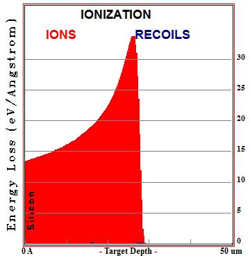
Energy Deposited per Unit Length from 5.5MeV Alpha Particles through Silicon
This plot assumes that no energy is lost as the alpha particles traverse the thin gold layer present for chemical isolation of the Am-241 source in commercial sources. The gold layer acts as a 'degrader' which shifts the above curve to the left.
Detecting Single Events
To measure the current pulses from the alpha particles passing through the photodiode, a transimpedance amplifier is required. My starting point for this was the picoammeter box I built to measure ionization current through a gas discharge tube. Since photodiodes are, as the name suggests, sensitive to photons, the sensor needs to be kept in the dark in order for the sensor to not be swamped by ambient light. Fortunately, I designed this circuit inside a metal box to shield it from stray electric fields, and that did a good job of keeping the sensor shielded from light as well.
Exposing the Photodiode
Normal photodiodes are molded in epoxy to protect the die. That epoxy packaging will stop all alpha particles before they reach the die. It typically requires high power lasers and / or nasty chemicals like fuming nitric acid to remove that epoxy packaging material, so I decided to instead cut open an old metal can package part with the hope that the die and lens were not molded together. I chose the TO-18 packaged BPW24R for this because of its reasonable availability on eBay (most metal can photodiodes on Digikey these days are either obsolete, non-stocking, or very expensive).
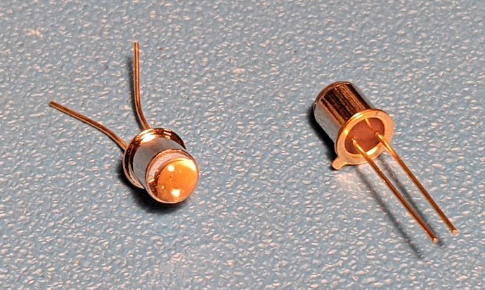
BPW24R Photodiodes
I cut the parts in half using a jeweler's saw. I destroyed the first part by cutting too close to the sensor, but I was successful on the second part.
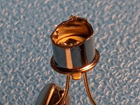
BPW24R Photodiode Cut Open
I soldered the part into the circuit and saw basically nothing. Just noise and a few pulses of only a few mV amplitude. Looking at the die, it appeared that it was covered in a some lacquer type substance (likely an anti-reflective coating), though. I next carefully attempted to scratch this coating away. I started as far from the bond wire as possible, and after removing about half of the material I stopped to test with a source again.

BPW24R Photodiode with Coating Partially Scrapped Away
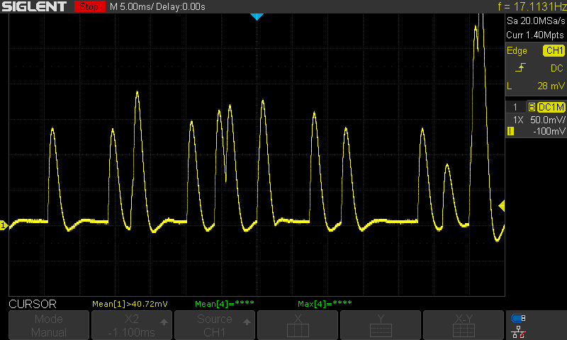
I soldered the part back into the circuit, closed up the box, and immediately saw clear events!
Alpha Particle Events
Optimizing the Response
Some amount of feedback capacitance is needed to stabilize the circuit. Too much feedback capacitance, and the output is overdamped resulting in a slow response time. Too little feedback capacitance, and the output is underdamped resulting in ringing and eventually oscillation. With just the right amount of feedback capacitance, critical damping can be achieved where bandwidth is optimized and there is no overshoot or undershoot in the transient response of the amplifier.
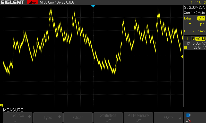
Very Overdamped Response
When used with a gas discharge tube, the bandwidth of the TIA is not a limiting factor because the tube itself has a rather long response time. For that reason, I placed a low leakage 22pF film capacitor in shunt with the feedback resistor on my early units to stabilize the circuit. That amount of feedback is quite excessive when used with a fast responding device like a photodiode, though.

Gimmick Capacitor (Across terminals of Blue 1Gohm Feedback Resistor)
High impedance circuits let you get away with unusual construction techniques. Two wires twisted together, sometimes referred to as a gimmick capacitor, can work great as low capacitance, low leakage adjustable feedback capacitors. The frequency response of such a capacitor is probably not great above the HF range, but when used in a high impedance low frequency circuit, it works just fine.
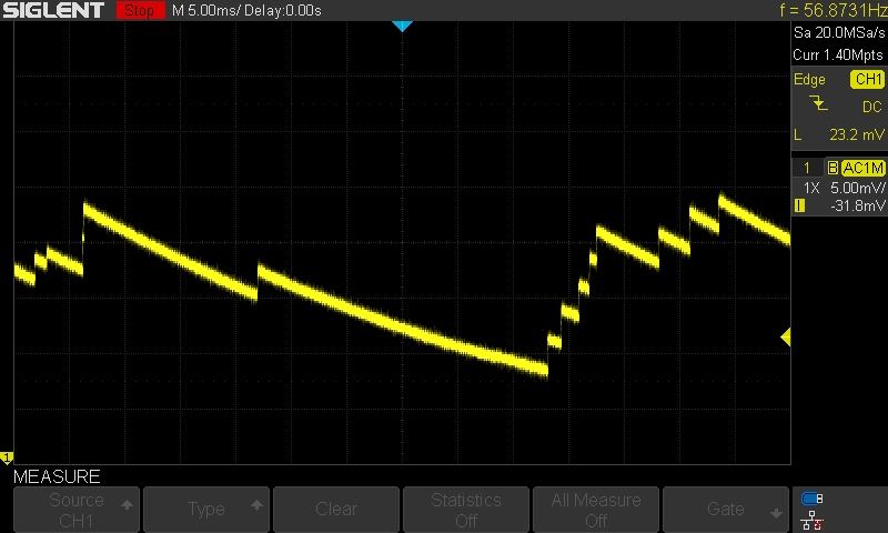
Slightly Underdamped Response
Using a gimmick capacitor allows me to tune the feedback capacitance on the fly by untwisting the capacitor until critical damping is achieved and then trimming the leads. These scope captures show the iterative process.
Critically Damped Response
Improvements
This circuit happened to work acceptably for this particular toy application, but it is very far from optimal in terms of number of events per second that it can handle without pileup and in energy resolution. A few easy changes can be made to improve the performance of this circuit.
Reducing Recovery Time
The faster the response time, the more events per unit time you can unambiguously detect. If a second event occurs before the amplifier has recovered from a previous event, the two will pile up. Pile up can to some extent be mitigated by additional pulse shaping stages as long as the rising edges are sharp, but for this simple application, the second event is just ignored because rising edges are only counted if the previous event has ended and the output has returned to near steady state. If the amplifier had a faster response time, I would be able to count more distinct events which would increase the number of random bits per second that the circuit produces.
Simulation Schematic for Feedback Resistor Options
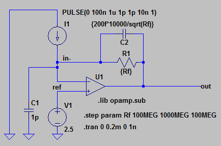
One way to reduce recovery time is to reduce the value of the feedback resistor. This has the effect of reducing pulse height, though. I simulated a few options and found that the required feedback capacitor for a critically damped response is pretty close to 1/sqrt(R_F) as you increase the value of the feedback resistor. Here is a simulation that sweeps the feedback resistor and feedback capacitor together from 100Mohm and 200fF to 1Gohm and 63fF. The 1pF simulated photodiode capacitance is obviously overly optimistic (the response is 5x faster than what I actually observe), but this simulation is still illustrative of the trade-off:
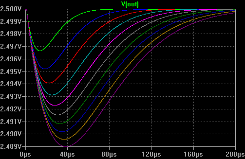
Simulation of 100M to 1G feedback Resistors
In order to preserve pulse height while using a lower value feedback resistor to speed up the recovery time, a higher bandwidth OP-AMP is required. The bandwidth of a transimpedance amplifier is limited by the GPW of its OP-AMP, the capacitance of the detector, and its own feedback capacitance. I selected LMP2231 for the TIA in the ionization chamber circuit because of its great DC performance (low input leakage and offset), but its GBP is pitiful (130kHz). For a single event detecting circuit, DC performance is irrelevant as the signal can be AC coupled. Another benefit of AC coupling is that the diode can be reverse biased; leakage current can swamp a DC coupled detector and since it is temperature dependent it causes baseline wandering as temperature changes. Reverse bias increases the width of the depletion region in the photodiode which reduces the capacitance and increases the response (more electron hole pairs per particle). Lower parasitic capacitance means that less feedback cap is required for stability which allows for a faster response.
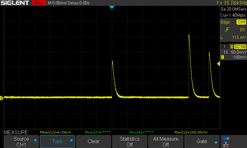
For a quick test, I compared LMP2231 with a 1Gohm and 10Mohm feedback resistor to OPA325 with the same feedback. OPA325 is a footprint compatible 10MHz GBP OP-AMP that I had laying around. I did not change the feedback capacitance for any of these tests -- I kept the same twisted wire gimmick capacitor. The output of the unmodified circuit (LMP2231 and a 1G feedback resistor) has an amplitude of 118mV (The probe settings are mis-configured and should be 1x, not 10x) with a total event time of around 3ms.
LMP2231 with 1G Feedback Resistor
Decreasing the feedback to 10M decreases the amplitude to 56mV, but the response time is improved to ~250us (and would be less if the compensation were updated).

LMP2231 with 10M Feedback Resistor
Next I swapped in OPA325. The response time with a 1G feedback resistor is pretty similar (2.5ms), but amplitude is noticeably higher (182mV).
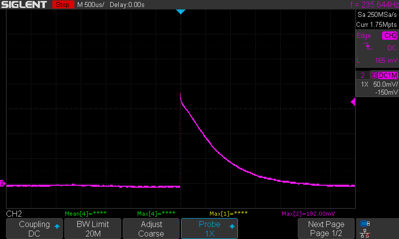
OPA325 with 1G Feedback Resistor
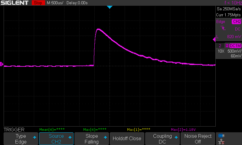
What sets the higher bandwidth OPA325 apart from LMP2231 is that the amplitude of its response is barely affected by the 10M feedback resistance while its response time is dramatically improved: Amplitude dropped ~2% while response time dropped 99% (30us). Note that for all of these captures I slowly increased the trigger level each time to capture only the highest energy single event since there are many events of intermediate energy that would make an apples to apples comparison of pulse heights impossible.
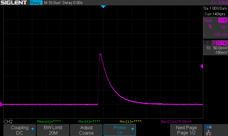
OPA325 with 10M Feedback Resistor
Reducing Noise
To further increase resolution, I would need to select a low noise (input current noise and input voltage noise) OP-AMP with a higher GBP. In order to detect gamma photons with a photodiode, you typically need a multi-stage amplifier, but since alpha particles are much higher LET, you can get away with much lower performance parts.
For the lowest possible noise, discrete components are used in front end amplifier circuits for nuclear detection. The technical term used is "Charge Sensitive Preamplifier" (CSP). The literature shows the output of these circuits as being similar to my early "very overdamped" screen captures since these circuits work like leaky integrators. In nuclear detection, these CSP circuits are followed by pulse shaping amplifiers and finally a "Multichannel Analyzer" (MCA) which bins the heights of the pulses into channels for spectroscopy purposes.
While I could extend this circuit to do alpha spectroscopy, that is beyond the scope of just using the detected events as a source of randomness. You can do fun stuff like estimating the age of Americium-241 samples (Am-241 decays to Np-237 which itself undergoes alpha decay but at a lower energy which makes its decays discernible from Am-241 decays).
Turning Detections Into Random Bits
When you flip a coin, the result is discrete; it is either heads or tails. When you observe a sample of radioactive material with a discrete time digital device, you see random events with a Poisson distribution. How do you decide what constitutes a 1 or a 0? One method is to measure the time between each event and then compare pairs of two. If the first time-between-event interval is longer than the second interval, the result is one, and if the second interval is the same as the first, the result is zero (If the intervals are equal, the pair is ignored). This method, which is used by HotBits produces one random bit per two detected alpha particles.
My alternative approach, which I am sure is not novel, is to instead look at the time index of each rising edge of the detector and use the LSB of that value as the random binary output. Which is to say, if the time index of the rising edge is even, the output is 0 and if the time index is odd, the output is 1. With a detector with a 10ksps sample rate, the sample period is 100us, if rising edges are detected at 500us, 5.4ms, 9.5ms (sample=5,54,93=1011,110110,1011101) and the output is 1,0,1. To validate this idea before implementing it on a microcontroller, I wrote a quick Python program to apply this algorithm to a CSV oscilloscope capture. The code and example data can be found here.

Portion of Oscilloscope Capture
Since I am only interested in upper case alphabetic characters, I only need to collect five bits per character. As those bits are collected, I shift them into an empty int. Once five are collected I discard any that are over 25 and add 'A' to any that are under 25 to shift the bytes up to the ASCII capital letter range. I could probably do something with the >25 words, but that would require care to avoid introducing bias into the data. For example: if I used took the collected bits and applied mod 25 to them, I would have a bias in the A-F range since those characters would appear twice as often.

Output of Python Script
Porting to STM32F103
I chose an STM32F103 because its USB interface to act as virtual serial port. This means that this board can be plugged into any computer or cell phone and immediately start streaming data with no special drivers. If I used an ATMEGA328P, I would need to add a separate USB to serial chip. The STM32F103 also has a faster core clock and higher performance ADC compared to ATMEGA328P.

Pin Assignment
There are no Arduino board support packages that I can find which enable USB VCP communications on STM32F103, so I used STM's development chain instead. STM32CubeMX creates a project template based on your desired features an pin assignments, and STM32CubeIDE lets you add your user code and upload to the microcontroller. I ended up using the amplified output connected to pin B0. With a well positioned 1uCi source, the box outputs a line of text every 1-2 seconds.
The user code here (what I added to the auto-generated template) is pretty simple and a close copy of the prototype Python code. All I had to do was drop it into the main function of the boilerplate files that the STM32CubeIDE created. Here is the full main() function:
int main(void)
{
  HAL_Init();
  SystemClock_Config();
  MX_GPIO_Init();
  MX_USB_DEVICE_Init();
  MX_ADC1_Init();
  MX_ADC2_Init();

  /* USER CODE BEGIN 2 */
  uint16_t index = 0;
  uint8_t workingByte = 0;
  uint8_t triggered = 0;
  uint16_t collected_bits = 0;
  uint16_t char_counter = 0;
  uint16_t string_counter = 0;
  char msg[]="ERROR ERROR ERROR ERROR ERROR\r\n";
  /* USER CODE END 2 */

  /* Infinite loop */
  /* USER CODE BEGIN WHILE */
  while (1)
  {
	index = !index;
    uint16_t raw;
    uint8_t addByte = 0;

    // Get ADC value
    HAL_ADC_Start(&hadc2);
    HAL_ADC_PollForConversion(&hadc2, HAL_MAX_DELAY);
    raw = HAL_ADC_GetValue(&hadc2);

    if(!triggered && raw <= 2000)
    {
    	triggered=1;
    	addByte = index<< collected_bits;
    	workingByte = addByte | workingByte;
    	collected_bits++;
    	if(collected_bits == 5)
    	{
    		if(workingByte<26)
    		{
    			msg[string_counter]=workingByte+'A';
				char_counter++;
				string_counter++;
    		}
			workingByte = 0;
			collected_bits=0;
    	}
    }
    if(triggered && raw > 2000)
    {
    	triggered=0;
    }

    if(char_counter==5)
    {
    	char_counter=0;
    	string_counter++;
    }
    if(string_counter==30)
    {
    	string_counter=0;
    	char_counter=0;
    	CDC_Transmit_FS(msg, strlen(msg));
    }
    /* USER CODE END WHILE */

    /* USER CODE BEGIN 3 */
  }
  /* USER CODE END 3 */
}