Cheap Ionization Chamber
2021
Ionizing radiation creates ion-electron pairs as it passes through neutrally charged matter. If this matter is a gas, you can pass a current through it and measure the relative intensity of the radiation. Ionization chambers are a common tool used in radiation measurement and detection, and like most scientific instruments are quite expensive off the shelf. As part of my job, I occasionally test electronic components in proton beams to assess their suitability for use on satellites (the Van Allen belts are full of trapped electrons and protons), so I decided to see if I could build an ionization chamber to record exactly when the proton beam is turned on and off during testing along with its relative intensity.
The currents produced by ionization chambers are quite small (pA to nA range), so the real challenge isn't building the ionization chamber itself since something as simple as a coffee can makes a fine ionization chamber; the real challenge is designing a circuit to measure that current which has good linearity, low offset, and reasonable dynamic range. That design of the picoammeter circuitry is detailed on this page.
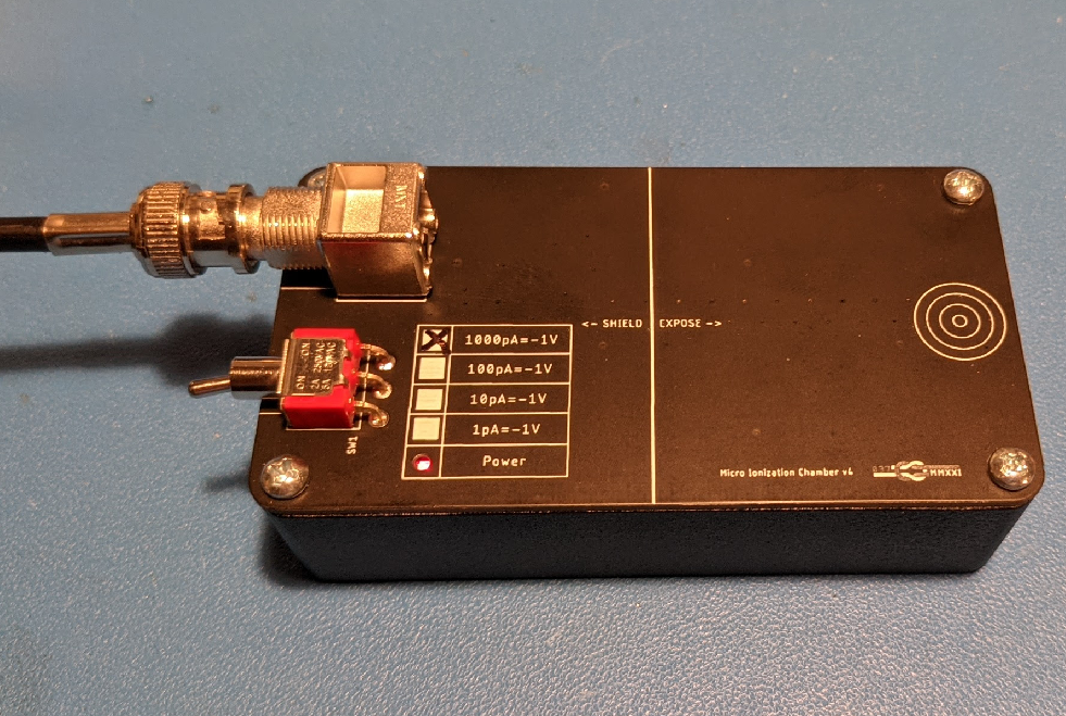
Ionization Chamber with Integrated Transimpedance Amplifier
The Ionization Chamber
My goal for this project was to only use parts available from an electronics distributer like Digi-key, and that included the ionization chamber itself. I considered a number options including EMI shield cans (and I actually initially started to design a photodiode based circuit), but after coming across this blurb in the Littelfuse Gas Discharge Tube product guide, I realized that gas discharge tubes would likely work in this application: "For voltages below the breakdown voltage, the gas provides a good insulator. Very low leakage currents (10-12A)[sic] occasionally encountered result from ionization by cosmic rays, high energy photons, etc"
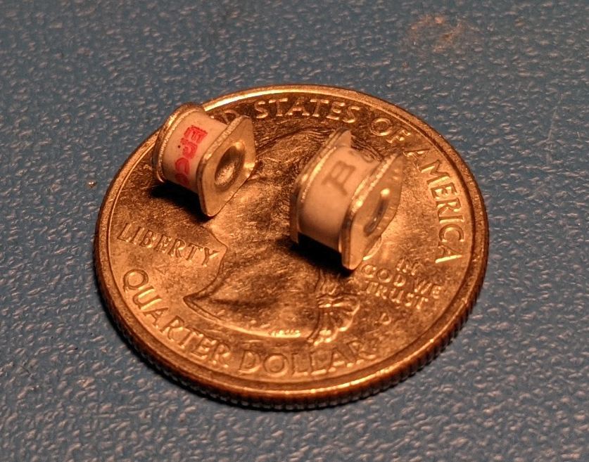
TDK B88069X5641T902 1.2kV GDT next to a Bourns 2093-300-SM-RPLF 3kV GDT
Gas discharge tubes are a type of surge arrestor. They have very low parasitic capacitance and very low leakage (under normal conditions) because they are fundamentally just air gaps. Large transient voltages cause these tubes to arc over into a low impedance state where they can handle large transient currents. The gas inside the tubes is typically neon, argon, or a neon argon mixture and it is typically at less than atmospheric pressure. The tubes themselves are hermetically sealed with glass or ceramic bodies sealed to the metal ends with good quality glass to metal seals.
I made sure to use tubes that were explicitly marked as 'non-radioactive' to make sure that there was no internal source of ionization that would reduce measurement accuracy at very low flux levels. It is my assumption that some (possibly older) tubes add a small amount of radioactive material to control the number of ions in circulation for a more consistent arcing voltage.
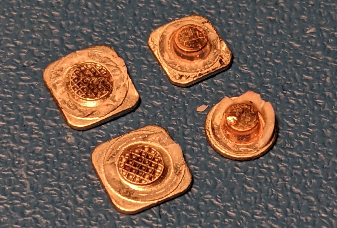
TDK B88069X5641T902 1.2kV GDT and Bourns 2093-300-SM-RPLF 3kV GDT Broken Open
The physical characteristics of the tubes along with gas pressure applied voltage determine the current that will be seen for a given ionizing radiation flux. With higher gas pressure, more ions-electron pairs will be generated in a given volume by a high energy charged particle. The greater the volume of gas, the more electron-ion pairs will be formed, but the electric field must be sufficiently strong to collect the ions and electrons before they recombine through random collisions. Thus, a tube with greater gas volume due to a greater air gap may produce a lower current than a tube with a smaller air gap if the applied voltage is the same. Ideally, an ionization chamber is operated in the saturation region: that is to say that the applied electric field is sufficient to collect effectively all of the ion-electron pairs before recombination.
Applying voltages higher beyond what is needed to place a tube into the saturation region will then not appreciably increase the current through the tube until the applied voltage is so great that multiplication results in a single electron-ion pairs cascading into many more. The electric fields required for that to happen are high enough that a parallel plate device will arc over even without incident radiation, so multiplying tubes are constrained to those with geometry that allows for non-uniform electric fields. The typical way of doing this is to use a wire centered inside a metal tube. The electric field at the thin wire is high enough to allow for multiplication, but the field at the inside surface of the tube is low enough that it does not arc over.
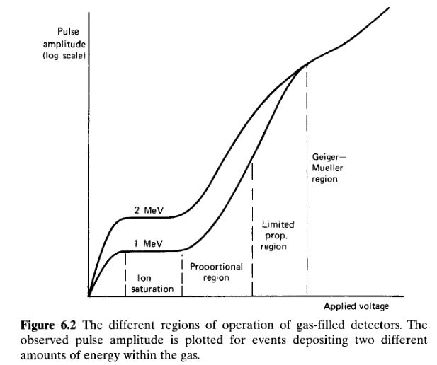
Electric Field vs. Pulse Amplitude - Knoll Radiation Detection and Measurement
The above plot is for proportional counters which provide a pulse response to single particle events, but the saturation region plateau is the same for ionization chambers. I did by first tests with a TDK B88069X5641T902 1.2kV GDT and had pretty good results. I then tried a Bourns 2093-300-SM-RPLF 3kV GDT, but it produced significantly less current at the same flux with the meager 6.5V bias voltage (measurement circuit explained in later sections) I applied to it. I found that it had resistive leakage that was significantly higher than the EPCOS tube as well, so I did not attempt to characterize it at higher bias voltages. The resistive leakage of the TDK tube, on the other hand, was below my measurement limit (100fA) even with a 600V bias. Greater sensitivity may be achieved with different tubes, but I have found that B88069X5641T902 is well suited for my application.
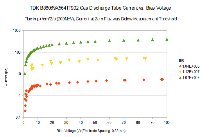
Applied Voltage vs. Measured Current at Different Proton Flux Levels
The above plot shows my actual current measurements with this tube under a three different flux levels. My initial picoammeter circuit design provided a bias of only 6.5V, so I modified the design to provide a ~100V bias from a 6V source.
Revisions
PCBs are so cheap now that I don't mind going through a few revisions for something simple like this. Each Revision cost ~$6 for 5 boards ignoring shipping, but I always lump multiple orders together.
Version 1: Duplicate a Reference Design
This was the proof of concept using LMC662 that showed that gas discharge tubes do in fact work as ionization chambers.
First revision with Offset Nulling
Version 2: Optimize Offset Performance
The next version implemented a lower cost and lower offset part and also added a second stage amplifier for additional gain. The default transfer function of the TIA is 1V/nA, but the second amplifier allows for even higher gain. I put check boxes in silkscreen to indicate the gain of a particular box. This is just for future flexibility -- additional gain is not needed for my nominal beam flux measurement use case. A normal non-inverting amplifier works fine here because the signal is referenced to virtual ground.
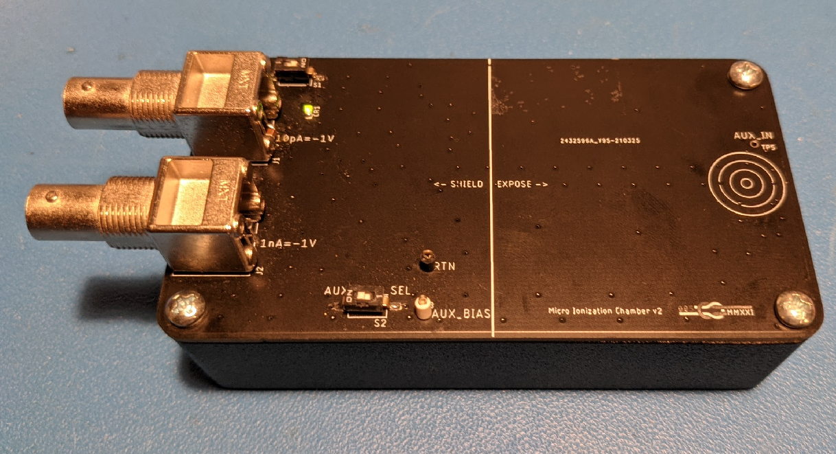
First revision with Offset Nulling
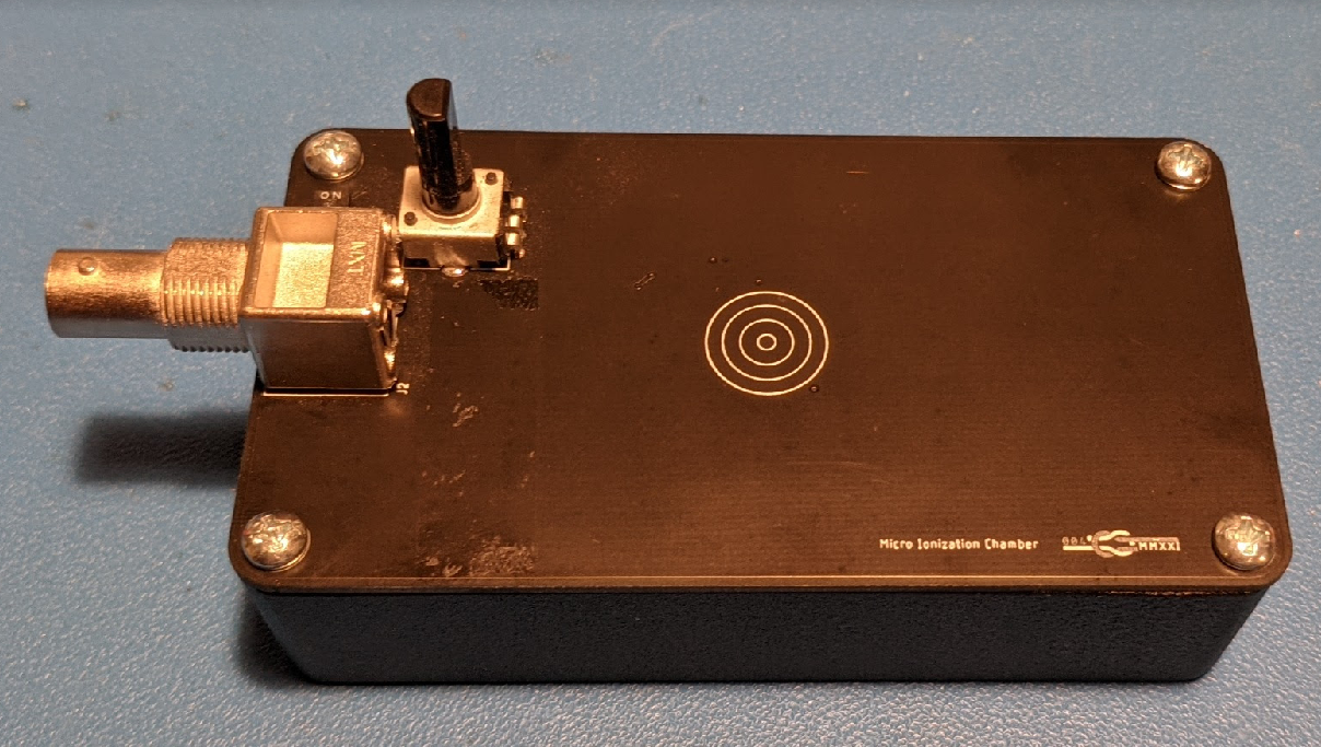
Version 3: Improve User Interface and add Bias Supply
Next, I changed the on switch to a through hole right angle toggle switch, and I fixed the LED by switching to a reverse mount part that shines out of a hole in the board. Since I also added an extra bias voltage supply, I was able to change the batteries to AAA and use SMD battery holders. Ultimately, I decided this was over-complicated and settled on adding a second 9V battery (rev4).
Cleaned up Design with Internal Bias Supply
Generating 100V from 6V is easy when your output current requirements are low; you can just use a boost converter in DCM. If you also want low quiescent power consumption, it gets a bit more complicated. I was planning to implement a hysteretic circuit that would allow the output voltage to vary +/-1V to limit switching loses, but I came across an example at the end of a Linear Technologies (Analog Devices) datasheet that showed how to run a voltage multiplier off of the switched node of a "Ultra-low Power Boost Converter".
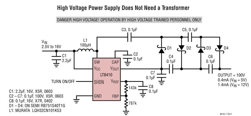
LT8410 Low Power Boost Converter Voltage Multiplier
I implemented this reference design and modified only the reference set resistor values and the switching diodes. The output voltage can be increased by adding additional multiplier stages. Here's a simulation with three stages instead of two:
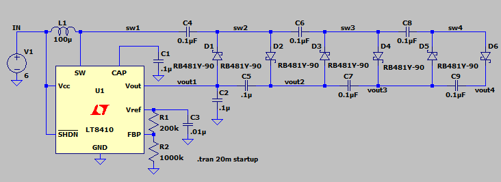
LT8410 Three Stage Voltage Multiplier
LT8410 has a 25mA switch current limit, so it takes some time to charge. Adding additional multiplier stages will increase increase start up time and quiescent current, but the number of stages can certainly be extended beyond four.
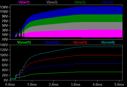
LT8410 Three Stage Voltage Multiplier Startup
I won't go into the details of voltage multipliers, but the main takeaway is that you can generate voltages higher than the maximum withstand voltage of any individual part in the circuit. The max voltage stress is the same for every diode: ~33V. The below plot shows how voltage is stepped up in each stage. Any boost controller IC could be used for this circuit, but I was attracted by the low quiescent current of LT8410 in particular.
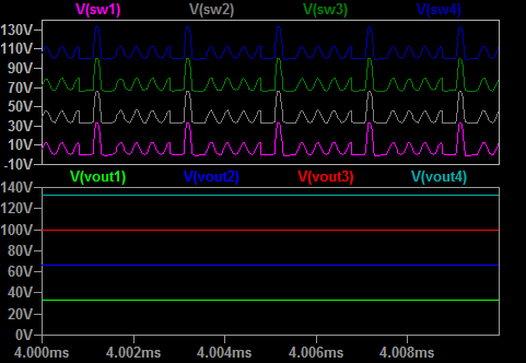
LT8410 Three Stage Voltage Multiplier Nominal Operation
Version 4: Replace bias supply with a second 9V Battery
Since a bias voltage of >12V reasonably linearizes the GDT, I made a version that uses a second 9V battery instead of an auxiliary supply. This second battery can be bypassed if the 6.5V bias provided by a single 9V is sufficient. The benefit of this version is that the board can be assembled more quickly and at a lower cost. The TID (total ionizing dose) performance of LT8410 is also not known, so this version should be able to withstand greater fluence (assuming that LT8410 is more sensitive to total dose than the OP-AMP).
(This is the same picture as version 3 because there are no external differences.)
Final Design