Pulse Dial to DTMF Tone Converter
2022
SchematicLayout
Rev2 EagleCAD Files
I like rotary phones, but no one has a landline anymore, and not all analog telephone adapters (what you need to interface an analog phone with a VOIP system) support pulse dialing. You can buy professionally assembled adapters, but where's the fun in that? There are a number of well designed DIY adapters, but they all use a bunch of through hole parts. Since I despise through hole parts that don't have a mechanical function, I decided to take the best documented DIY project and re-design the board to use surface mount parts.
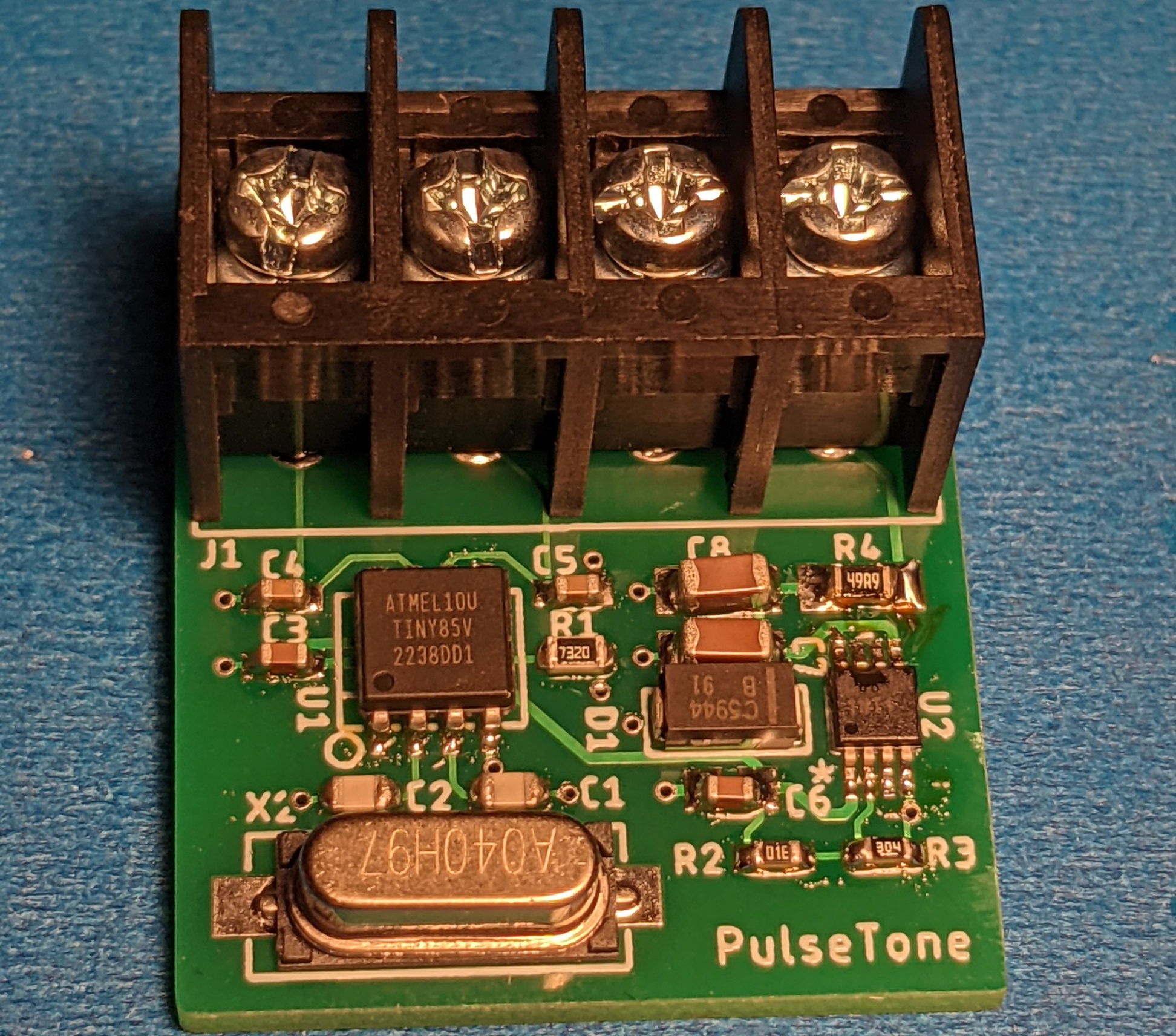
Assembled Pulse-to-Tone Converter
I changed the input linear regulator, but my linear regulator is not 'better' than L78L05 for this particular application. It requires more input and output cap (which attenuates AC on the phone line and reduces volume), and its higher voltage rating is unnecessary since the load of the phone drops line voltage to ~7. I just happened to have a bunch of this part on hand. All other changes were just to use surface mount parts.
How it Works
The ATTINY85 outputs DTMF tones on PB0 as a PWM waveform. This tone is coupled to the phone line indirectly by modulating the current draw of circuit. Because this circuit is powered by the phone line, AC current drawn through the linear regulator is coupled into the phone line. The amplitude of the tones can be adjusted by adjusting the value of R1.
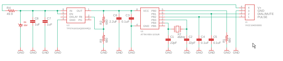
Pulse to Tone Schematic
The code on the ATTINY85 was based on a DTMF App note by Atmel and further developed by Boris Cherkasskiy, , Arnie Webber, , and finally by Matt Millman who added speed dial and other features.
To get this code onto the ATTINY, I used an Arduino Uno as a programmer using the example Arduino ISP sketch. This sketch is flashed to the Uno using the Arduino IDE; the rest of the programming is done with AVRDUDE. The rotarydial.hex file is not all that you need to program on the ATTINY85: you also need to set the fuse bytes. The two below commands should properly program the micro-controller for this project:
    avrdude -P COM16 -b 19200 -c avrisp -p attiny85 -v -e -U flash:w:rotarydial.hex
    avrdude -P COM16 -b 19200 -c avrisp -p attiny85 -U lfuse:w:0xfd:m -U hfuse:w:0xdf:m -U efuse:w:0xff:m
I initially programmed only the .hex to the microcontroller. I did get a tone when a digit was dialed, but it was the wrong frequency (audibly too high). After a bit of debugging, I determined the the fuse bits were wrong. After I set those, the board worked as it should.
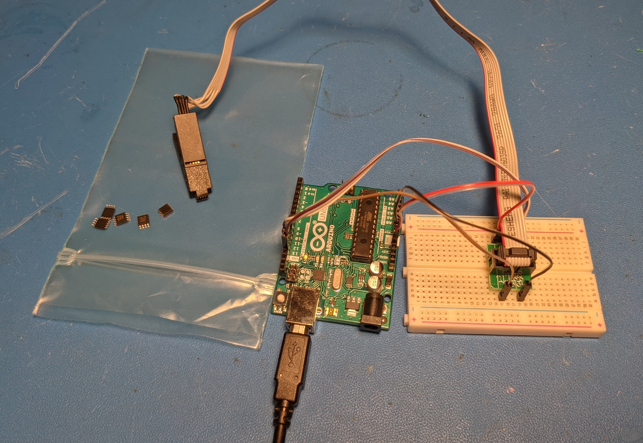
Programming Setup
I used a $7 programming socket from Amazon to interface with the SOIC-8 package ATTINY 85 chips. Despite the ling cable length, the parts all programmed just fine.
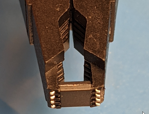
Programming Clip with DUT
Wiring of these phones varies, but for this phone, I hooked up the adapter in the following way. I first found the negative input line. I connected this as the ground of the board. Phones use a -48V voltage, but you can set the ring (-48V) side as the ground of the phone. I next found where the positive (tip) side of the line is connected after the hook switch. This way, the adapter board only loads the line when the phone is off-hook and the board's linear regulator only sees the voltage of the line after the phone is loading it (~7V with my ATA). That handles power. For the rotary dialing interface, I isolated the dialing lines from the rest of the phone and connected the common ground wire of the dial and pulse lines (dial is when you pull the dial back, pulse is the interrupted pulses when you release the dial) to the ground of the adapter board. I then connected these lines to their respective inputs of the adapter board. The ATTINY has internal pull-ups, to the micro-controller can discern when one of its inputs has been shorted to ground.
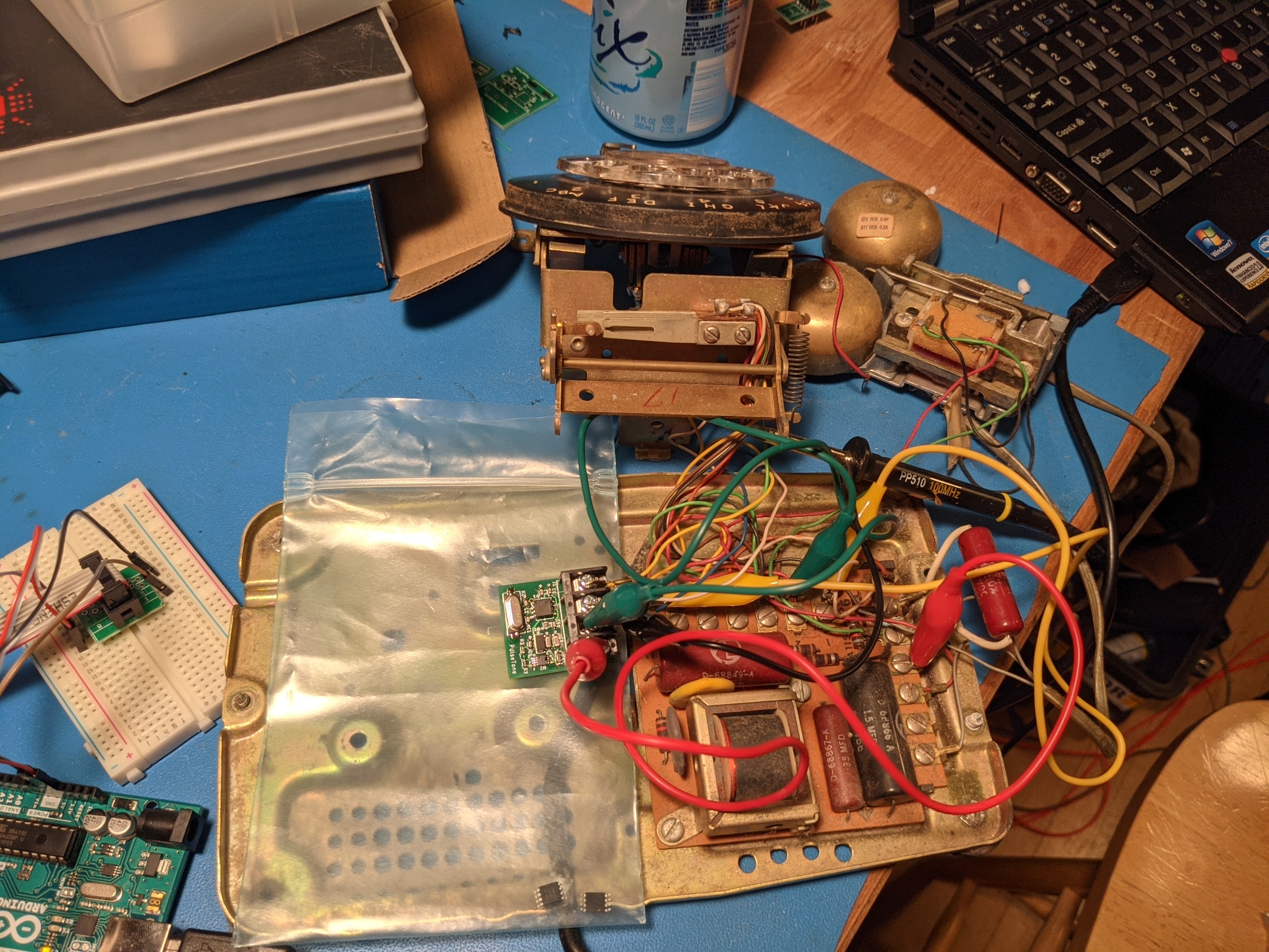
Test Setup
I verified functionality with allegator clips and then wired everything up permanently. I placed the adapter board in a plastic ESD bag to insulate it from shorting out (I could not find my Kapton Tape).
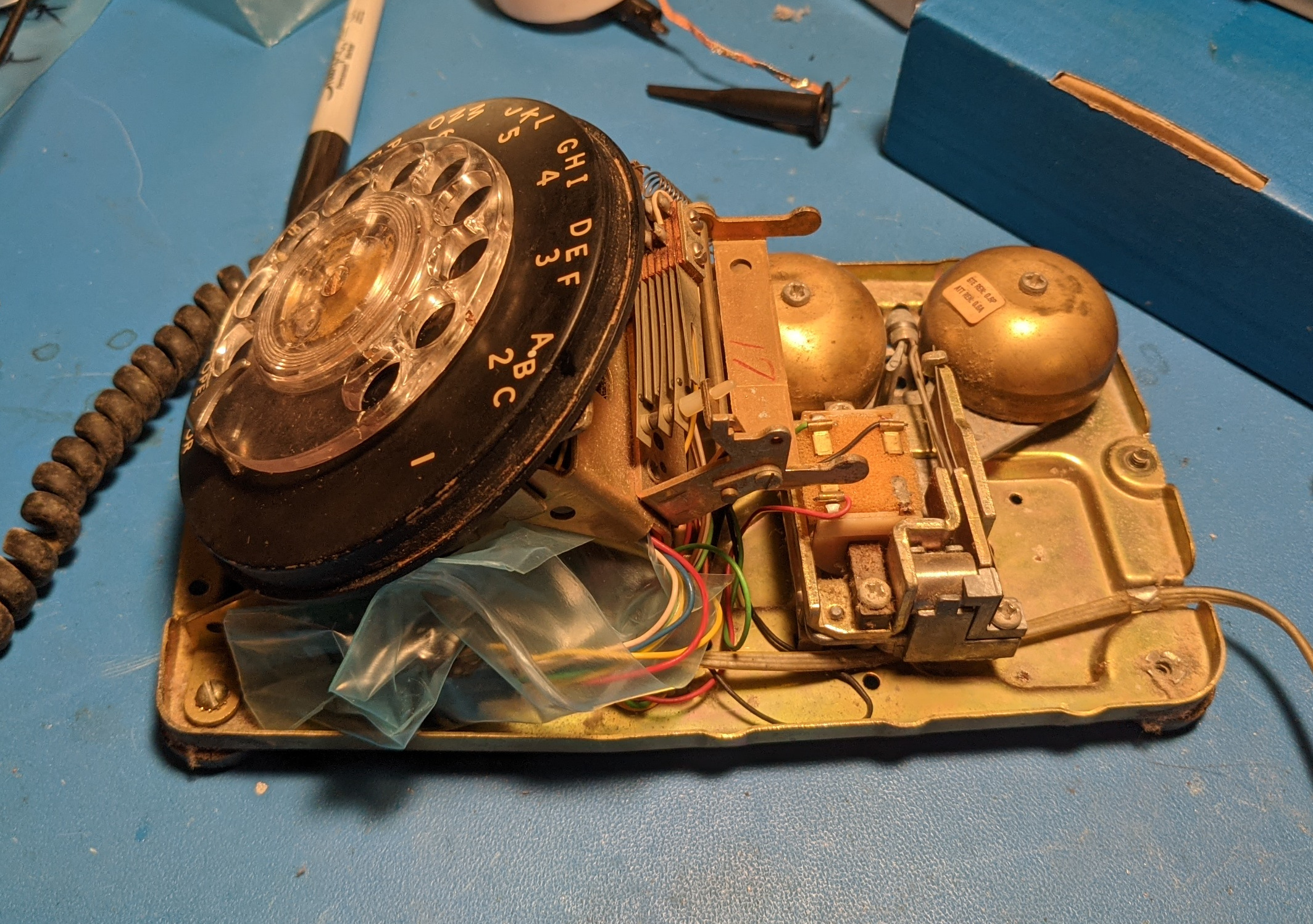
Assembled Phone with Adapter Board prior to Final Close-out
While I do have an analog telephone adapter (ATA) that supports pulse dial, this converter is quite convenient because it supports speed dial. If you hold the dial at the fingerstop for two seconds, wou heat a beep. Releasing the dial at this point will invoke the speed-dial setting of the associated digit. To set the speed-dial numbers, you hold the dial at the fingerstop for four seconds. You first hear a single tone and then two beeps. After the two beeps, you can dial the number that you want to save and then hang up. The phone will rapid-fire send teh speed-dial DTMF tones when the number is invoked after the two second beep in the future.
Western Electric Model 554 Instructions
After installing this adapter in a rather crusty Automatic Electric desk phone, I next installed one in the Western Electric Model 554 Wall phone in my kitchen. This phone as a model 425 network (the metal box with screw terminals that contains the hybrid and other electrical passives).
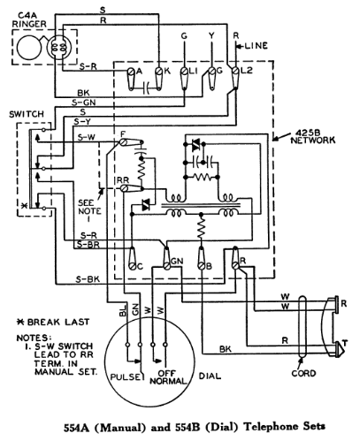
Western Electric Model 554 Wiring (source)
Four wires connect the dial to the phone. Two of these wires (both white) connect to a switch inside the dial that is open when the dial is in the full counter-clockwise position (at rest). Then this switch is closed (when the dial is turned), the speaker in the handset is shorted out to mute it. This prevents the loud clicks of dialing from being heard by the dialer. The other two wires (green and blue) connect to the switch that is pulsed open a number of times corresponding to the dialed digit when the dial travels clockwise after it is released. This pulse switch is closed otherwise, and it is necessary to install a jumper between the 'F' and 'RR' terminals of the 425 network for the phone to continue to have audio after the dial is disconnected.
Western Electric Model 425J Network Diagram
Instructions:
- Disconnect the four wires coming from the dial from the network. These are the wires connected to 'F', 'RR', 'GN' and 'R' terminals.
- Install a jumper wire between the 'F' and 'RR' terminals.
- Connect the green wire and either of the white wires coming from the dial to the 'GND' terminal of the pulse-to-tone adapter board.
- Connect the other white wire coming from the dial to the 'DIAL/MUTE' terminal of the pulse-to-tone adapter board.
- Connect the blue wire coming from the dial to the 'PULSE' terminal of the pulse-to-tone adapter board.
- Install a jumper wire between the L1 (ring / -48V) terminal and the 'GND' terminal of the pulse-to-tone adapter board. There will now be three wires on the 'GND' terminal.
- Install a jumper wire between the F (tip line after hook switch) terminal and the 'V+' terminal of the pulse-to-tone adapter board.
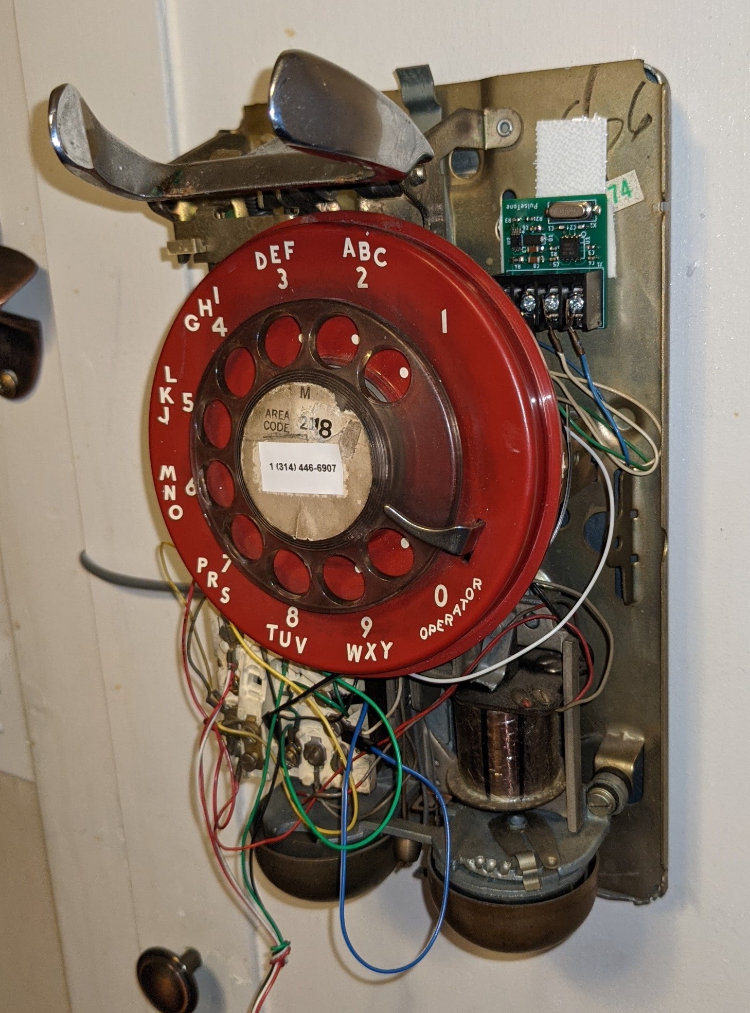
Installed Adapter Board
I had more room to work inside this phone than the desk phone, so I was able to nicely mount the board to the baseplate using 3M Command Strips.