Four Phone DNVT Switch
2022
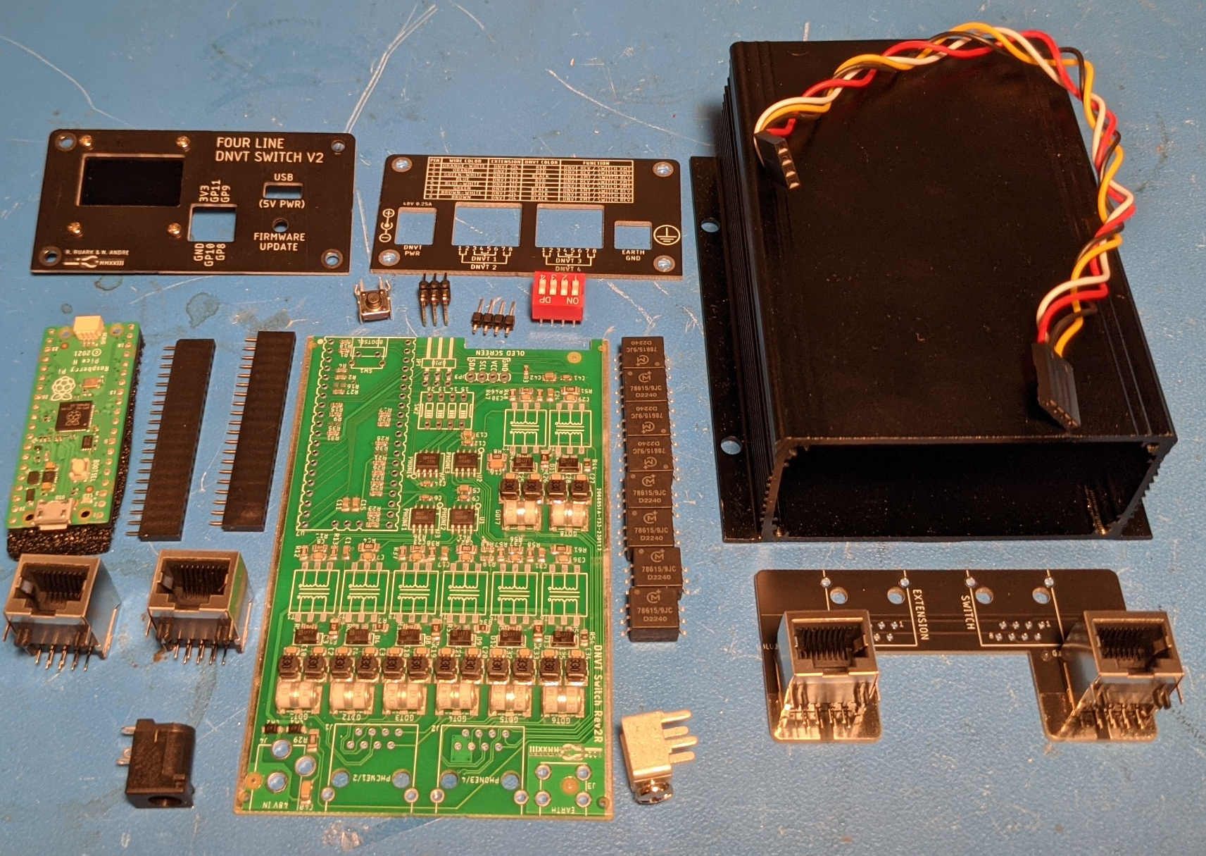
After verifying the hardware interface to the phones and reverse engineering how to control them using a single phone interface board, I designed a four phone switch. Four phones was chosen because it fit all the personal use cases I could imagine for these phones, and, more importantly, because of limitations of the RP2040 microcontroller on the Raspberry Pi Pico board. RP2040 has a unique PIO (Programmable Input Output) peripheral which has eight state machines that can be used to encode and decode Differential Manchester code. Each phone requires two of these state machines: one for receive and one for transmit.
V2 DNVT Switch
As implemented now, the switch supports calling any extension from any other extension and is able to play a few pre-recorded messages. The code that Nick Andre put together to make all of this happen can be found here. With a bit of software work, additional functionality could be added with no hardware changes by sending data over the USB port or the GPIO pins exposed on the front panel (there is also a DIP switch for configuration inside). With the right code additions, more than four phones could be supported. For example, multiple switches could connect as SPI slaves to a second board that handles call switching between slaves. Alternatively, the switch could connect over USB to software running on a PC to bridge the DNVTs to a VOIP system.
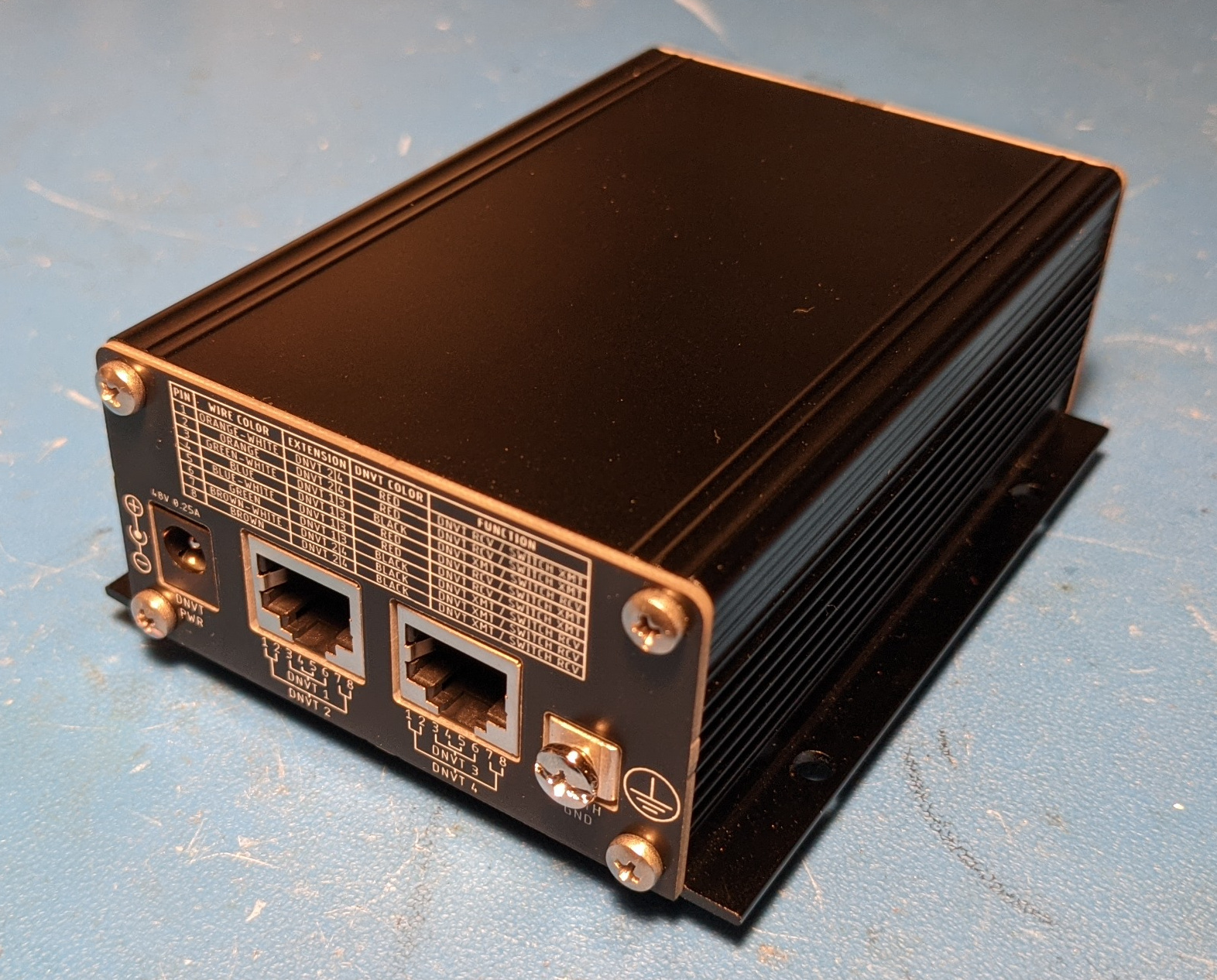
Back Side of V2R Switch
Versions
I ended up making a few versions of the switch:
- V1: LED Status indicators and Wire-to-board Connectors
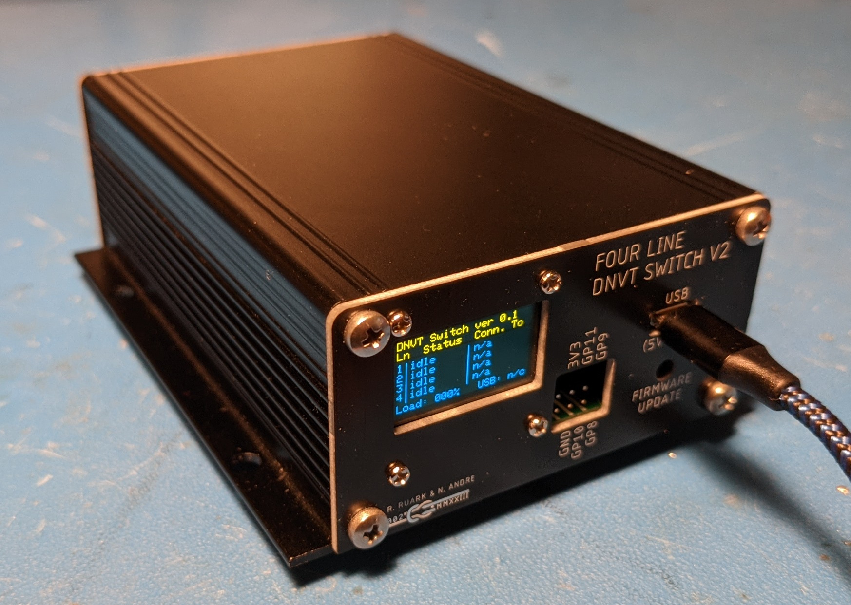
- V2: OLED Screen for Status and Wire-to-board Connectors
- V2R: OLED Screen for Status and RJ45 Connectors
- V2T: OLED Screen for Status, Wire-to-board Connectors, and Through Hole Transformers
- V2RT: OLED Screen for Status, RJ45 Connectors, and Through Hole Transformers
V1 PCBA and Box Showing Test End Plate 3D Print
Selling assembled boards without having them tested for Part 15 compliance would violate FCC regulations, so I will only offer these switches for sale as kits that the end user must solder together and assemble. I also have little interest in manually assembling boards to sell for a hobby project. I didn't design these switches to make money, but I would like to help others use their DNVTs by making kits available.
Design
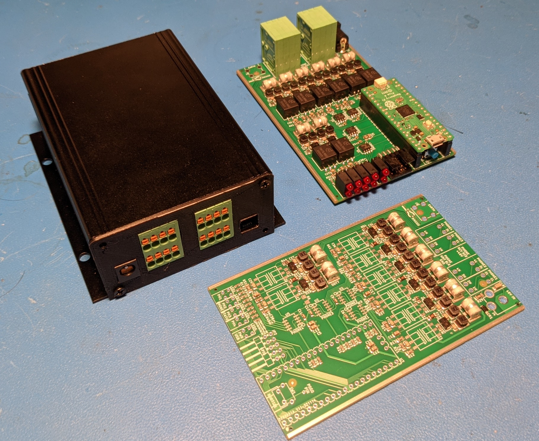
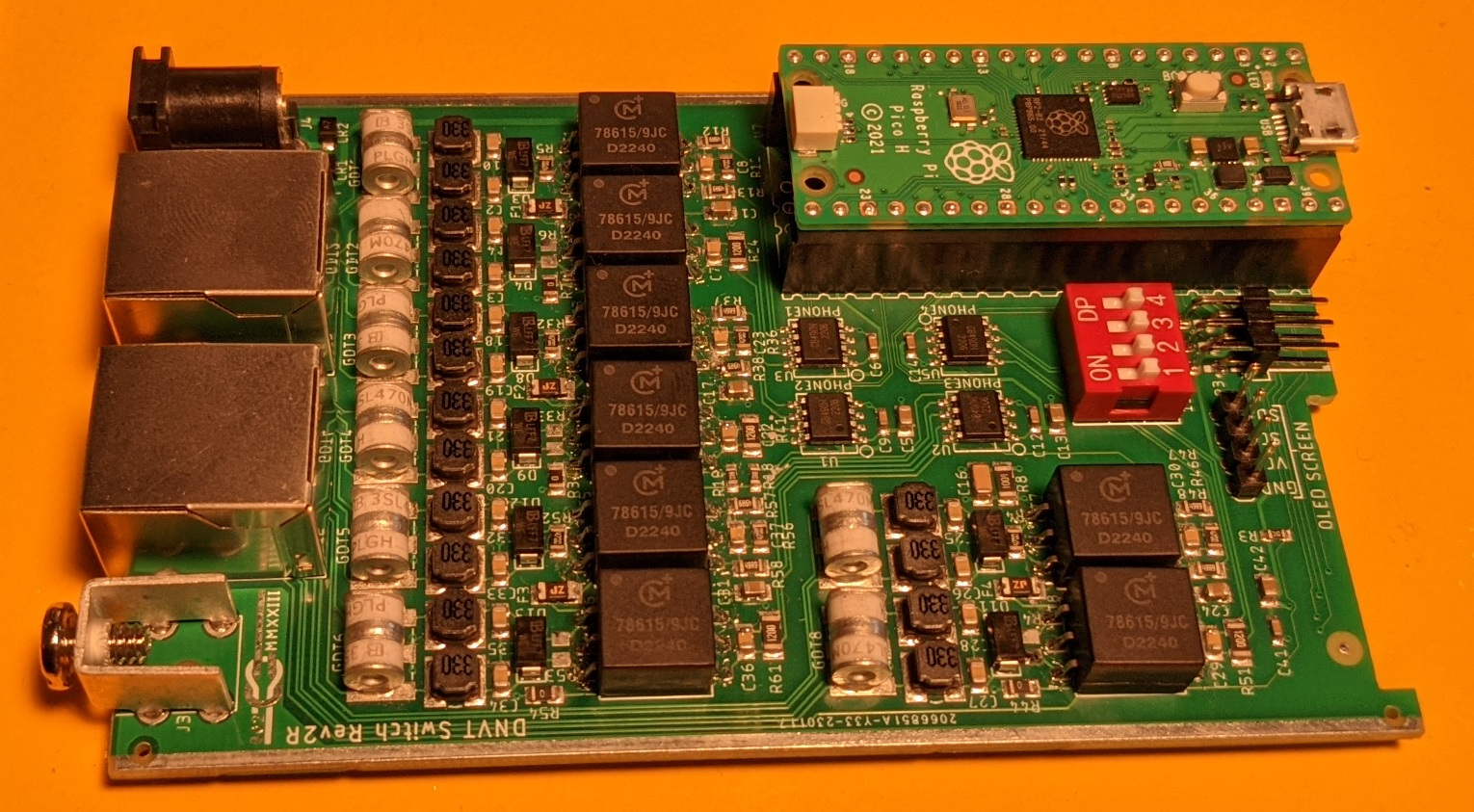
The switch PCBA consists of fours instances of the interface circuit, A Raspberry Pi Pico, and a handful of connectors. from the All of this hardware is open source, so if you want to make your own modifications to the boards or just place your own orders for the PCB/As, have at it. All of the design files can be found here. I doubt any large market exists for these phones, but if some company would like to take over this project and get the boards certified, I would be happy to support them in doing so. For the time being, the boards will be available in kit form only.
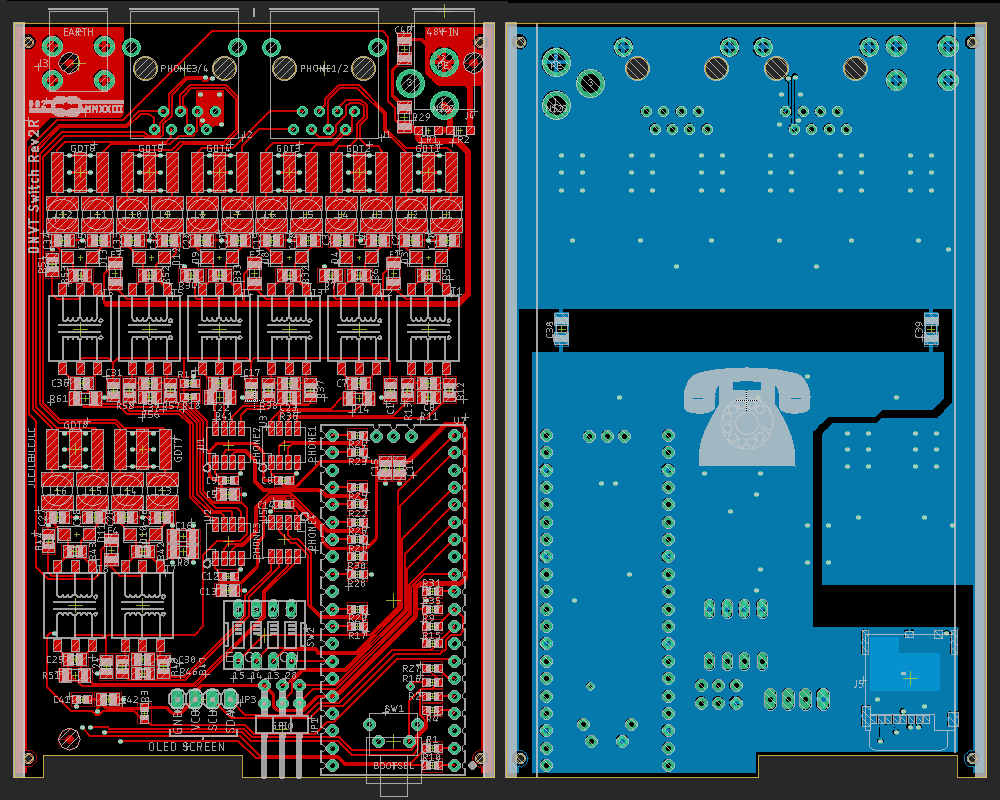
Top (left) and Bottom (right) of V2 Switch PCB
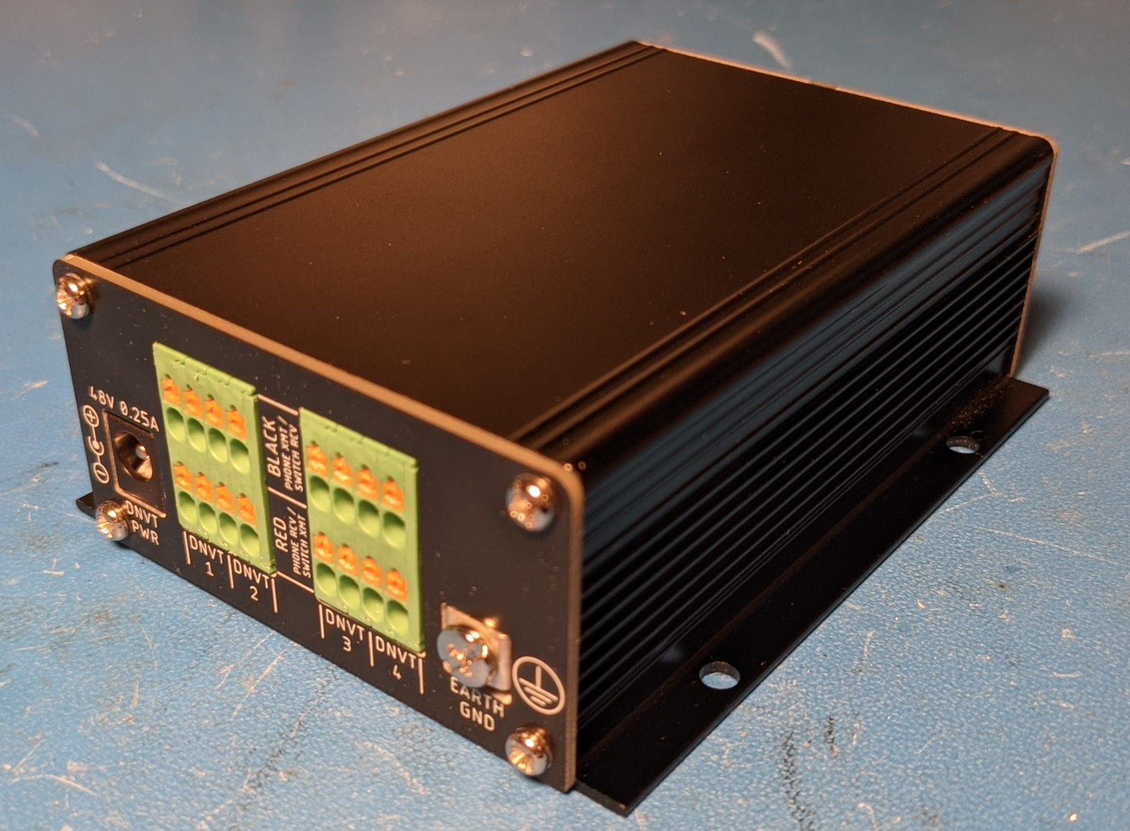
The switch is designed around an extruded aluminum project box from MWRF Source. The main board slots into the card guides of the enclosure, and custom end plates keep the PCB in place. PCBs are so cheap these days that they are the best way of building professional looking instrument face plates in low volumes. PCBs come with precise panel cutouts, holes, and silkscreen text at no extra charge, and 1.6mm FR4 laminate is pretty strong. Ten FR4 PCBs with a lead free finish cost $6.10 from JLC PCB, and for $7.50, you can get ten made on an aluminum substrate. I've had black soldermask on the Aluminum boards get scuffed during shipping, and the option to have paper placed between PCBs is greyed out on JLCPCB's ordering page, so I've stuck with FR4 for these panels. I've also seen board routing defects on aluminum boards that I've never seen on aluminum.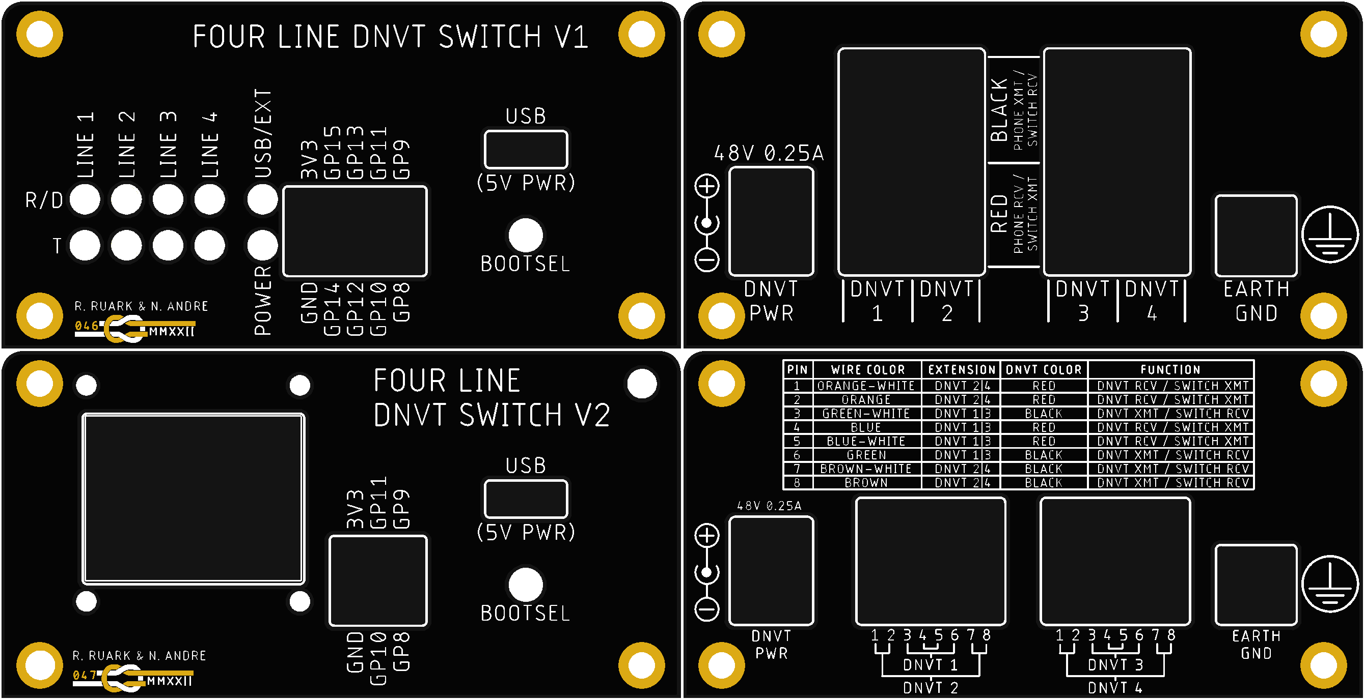
Top: Front and Back Panel of V1 Switch. Bottom: Front and Back Panel of V2 RJ45 Switch
Other Details:
- I included a right angle 6-32 screw lug for grounding, but as I detailed on the physical interface page, this only exists to protect the switch.
- There was just enough room to mount an OLED screen on the front panel, but I had to give up some of the pins on the expansion header to do so. It is held in place with M2 machine screws and bolts, and is connected to the main board with a four-pin standard space jumper.
- The BOOTSEL pin of the Pico is not broken out to a pin, but one of the GPIO pins is monitored in software and USB update mode will be triggered if the button tied to this GPIO is pressed.
- I initially tried to be clever and connect to the BOOTSEL test point on the bottom of the Pico with a pogo pin, but the height was a bit too much to make this work reliably.
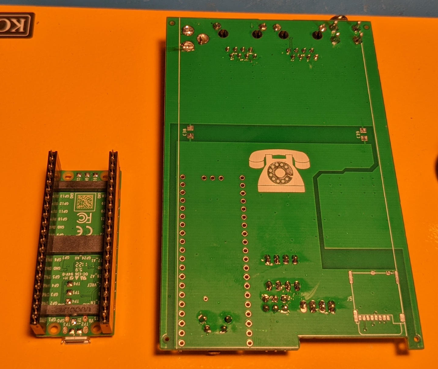
Back Side of V2 Switch
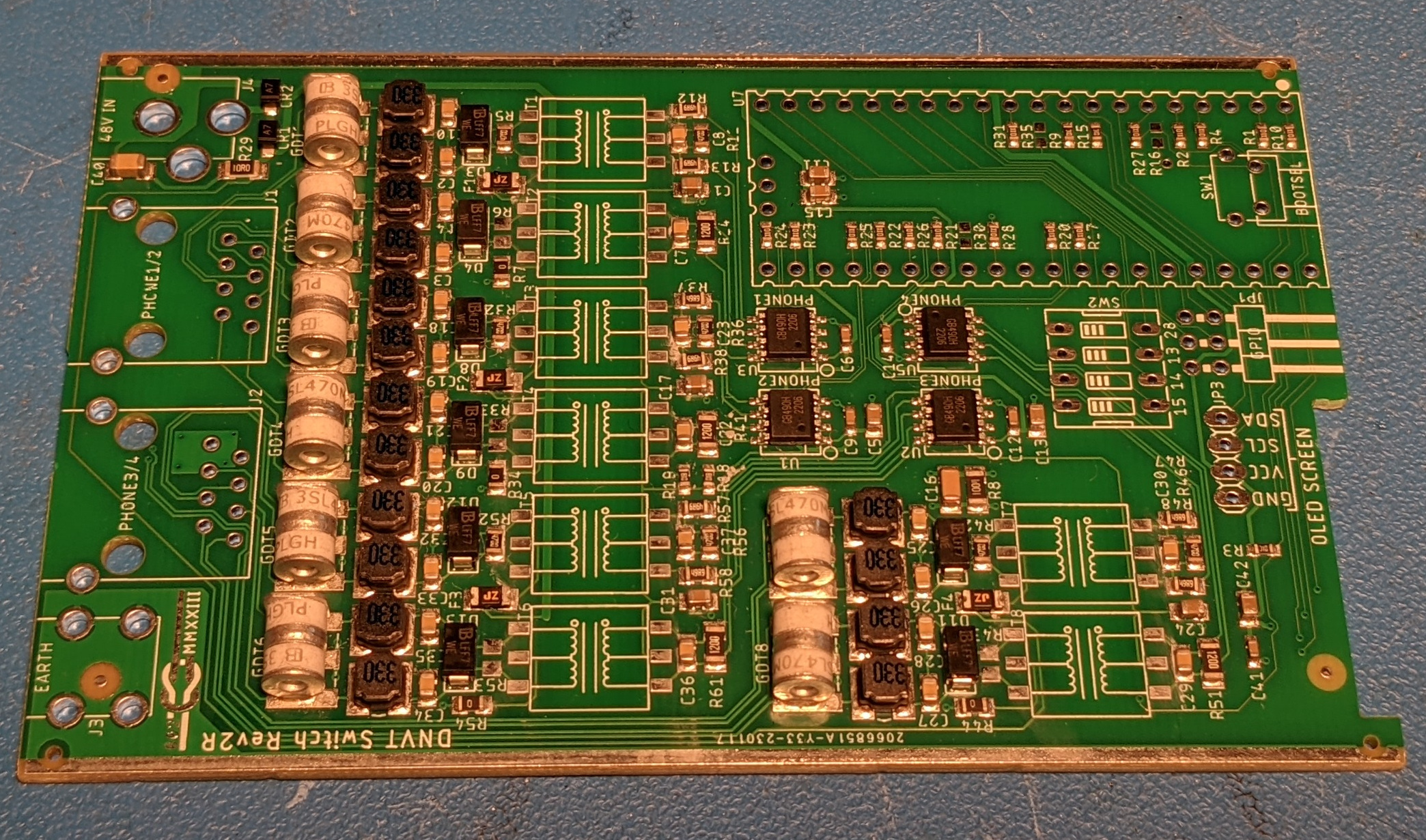
PCBA Fabrication and Assembly
All of the PCBs for this project came from JLCPCB. They are incredibly cheap and have an interactive ordering interface that puts US fab houses (aside from OSHPark) to shame. Advanced Circuits could learn a thing or two from them (Advanced's ordering page is one step above faxing them an order form and supplying the Gerber files on microfilm). JLCPCB also offers an inexpensive assembly service that I tried out for the first time with this project. They provide scrips to run in EagleCAD to generate the placement and BOM files that you can directly upload to their website. I was blown away at how easy it was to place an assembly order, and will be having most of my personal PCBs assembled by them instead of hand assembling for now on. You are able to interactively confirm parts placement using a 3D rendering of your design and are able to fix any placement or rotation issues on the fly. You can also pay $0.45 for one of their engineers to confirm the parts placement which is a no-brainer.
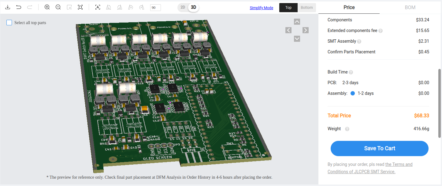
JLCPCB Placement Confirmation Page
There are two types of parts in JLCPCB's library: basic and extended. With basic parts, you pay for the cost of the components and $0.0017 per joint. With extended parts, you also pay an additional $3 per BOM line (presumably because they have to swap in or load different feeders to their pick and place machine). This design has five extended parts (the TVS diodes, The polyfuses, the GDTs, the inductors, and the RS422 transceivers), so the additional fee was $15.65. I don't know where the additional $0.65 came from, but I'm not about to complain. There is also $8 setup fee and a $1.50 stencil fee. The parts for five boards cost $33.24, so the grand total for five boards (PCB + parts + assembly) was $68.33 (13.66 per board).
Partially Assembled V2R PCBA As Received from JLCPCB
JLCPCB's export scripts omit through hole parts entirely and they do not have an appropriate transformer in their library, so the only parts that I have to solder myself are the through hole connectors and the transformers. For resistors and capacitors, JLCPCB's BOM matching tool is able to pick out appropriate parts on its own based on the footprint and value, but for more specialized parts you can add the JLCPCB part number for the specific part that you desire to the BOM prior to uploading. There are a lot of parts in their extended library, but it takes some patience to find exactly what you're looking since you need to figure out what category the parts are in and then use the less-than-perfect parametric search tool. I didn't include the RS422 transceivers on the assembly order until the RJ45 version of the switch because they lumped RS422 and RS485 transceivers into the same category preventing me from finding an appropriate part. After searching through a dozen datasheets (most in Chinese), I found GB490H which has been working just fine.
GB490H RS422 Transceiver Datasheet
In addition to the assembly being cheap, the parts themselves are also cheap. Its actually cheaper to have JLCPCB assemble the board with their parts than it is to buy a bare PCB and assemble it with parts from Digi-key. For the through hole parts, I bought all that I could from LCSC due to the cost savings. For example, the headers for the Pico cost $2 each on Digikey and $0.17 each on LCSC.
Kit Assembly Instructions
The order of assembling the through hole parts doesn't matter nor does the orientation of the transformers. The only things to note are that you should make sure to keep the barrel jack straight while soldering since the holes are oversized and that it helps to plug the Pico into the headers prior to soldering the headers in so that the headers stay straight as they are soldered. Helping hands or a friend make assembly easier, but you can definitely assemble a board with just a stick iron and some rosin core solder.
DNVT Switch Assembly Kit
BOM: (LCSC, Digi-Key)
- Aluminum Box
- V2T or V2TR Switch PCBA with Surface Mount Parts Already Assembled.
- V2 Front Panel PCB with OLED Screen Installed + 4-pin jumper
- V2 or V2R Back Panel PCB
- 2x 20 Pin female Headers (C5224030, 952-1905-ND)
- Four Pin Male Header (C2691448, 2057-PH1-04-UA-ND)
- Eight Pin Right Angle Male Header (C2935935, 2057-PH2RA-06-UA-ND)
- Four position DIP Switch (C962226, 2449-KG04E-ND)
- Right Angle Tactile Switch (C2845272, P10880S-ND)
- 2x RJ45 Jack (C708610, AE10387-ND) OR 2x Wire-to-Board Connectors (C2975064, 277-10317-ND)
- 6-32 Screw Terminal (36-8190-ND)
- 2.5mm Barrel Jack (1939-G-1005B-ND)
- Raspberry Pi Pico H (2648-SC0917-ND)
- 8x 78615/9C Pulse Transformers (811-1261-5-ND)
- 48V Power Supply (993-1303-ND)
- 8x M3 Screws (H742-ND)
Bottom of Partially Assembled PCBA
Fully Assembled V2R PCBA