1kWh Portable Power Pack
2019
When I was a kid, I found three 12V AGM batteries on the side of the road. I built a box with fuses, an ammeter, and a power inverter for them. I used this power box to run fans and lights and to charge a laptop at the scout camp I worked at. This box was very heavy and only had a capacity of ~350Wh when I first built it -- it lasted three summers before no longer holding a useful charge. I wanted to rebuild the box using lithium batteries, but it would have cost too much then (2013). Prices have since gone down quite a bit from the ~$0.50/Wh I would have had to pay for cells back then.
Jump to 2019: I want a portable battery pack that can charge a cell phone and run my custom power inverter, and lithium batteries are now cheap and plentiful.
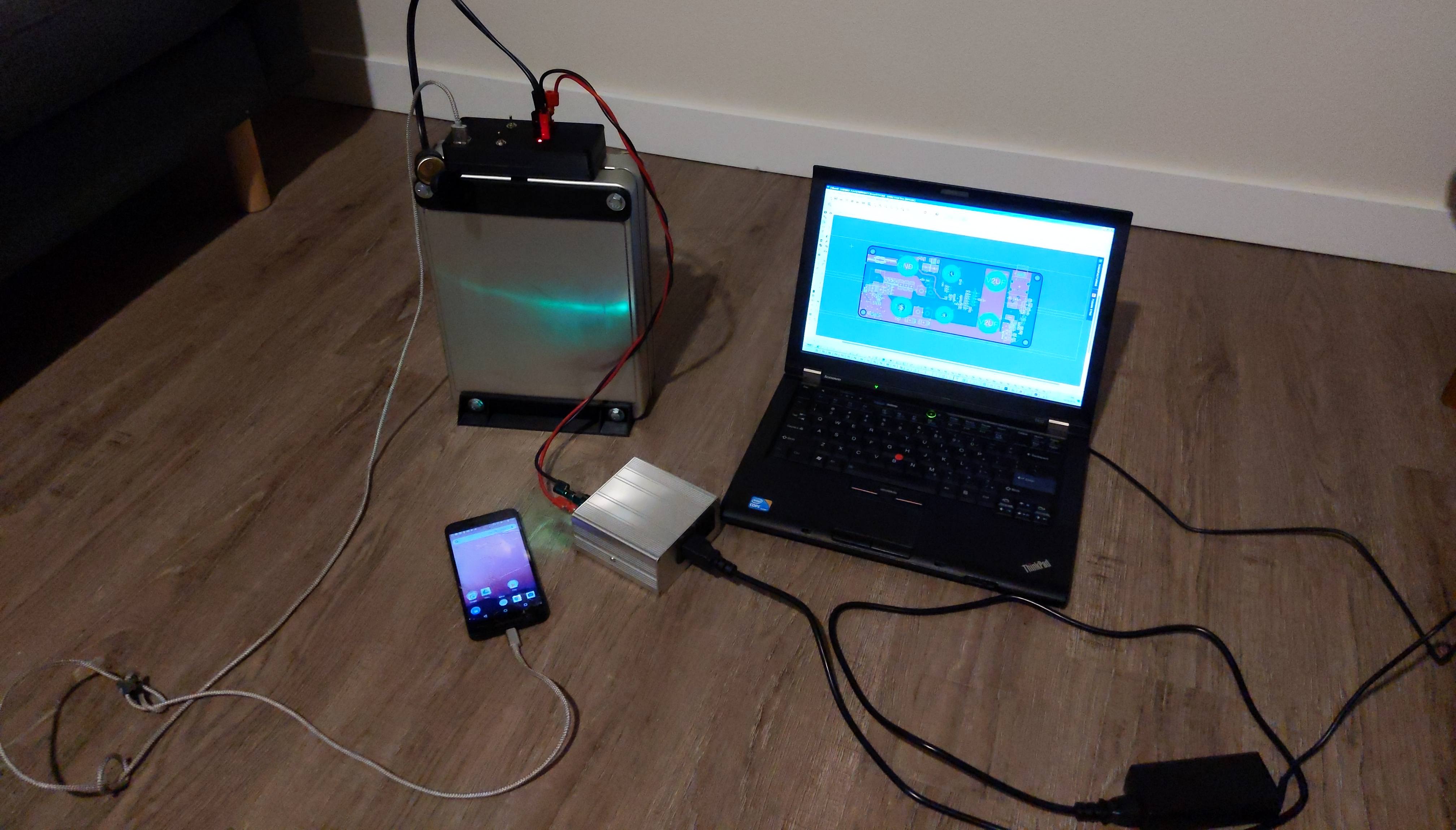
Finished Pack With Loads
SchematicLayout
EagleCAD Files
3D Print Files
Background
Nissan Leaf batteries are the cheapest source of lithium ion watt-hours at around ~$0.12/Wh. For comparison, used Tesla batteries and new NCR18650BD 18650 cells sell for ~$0.20/Wh, used CALB LiFePO4 modules sell for $0.30/Wh, and flooded lead acid Trojan batteries cost ~0.08/Wh. In addition to low cost, the Nissan Leaf batteries are also in a convenient package. Bare 18650s need enclosures and tabbing wire. Tesla battery modules are too large for throwing in a backpack. LiFePO4 Prismatic cells are a convenient form factor, but they are more expensive and less energy dense.
Implementation
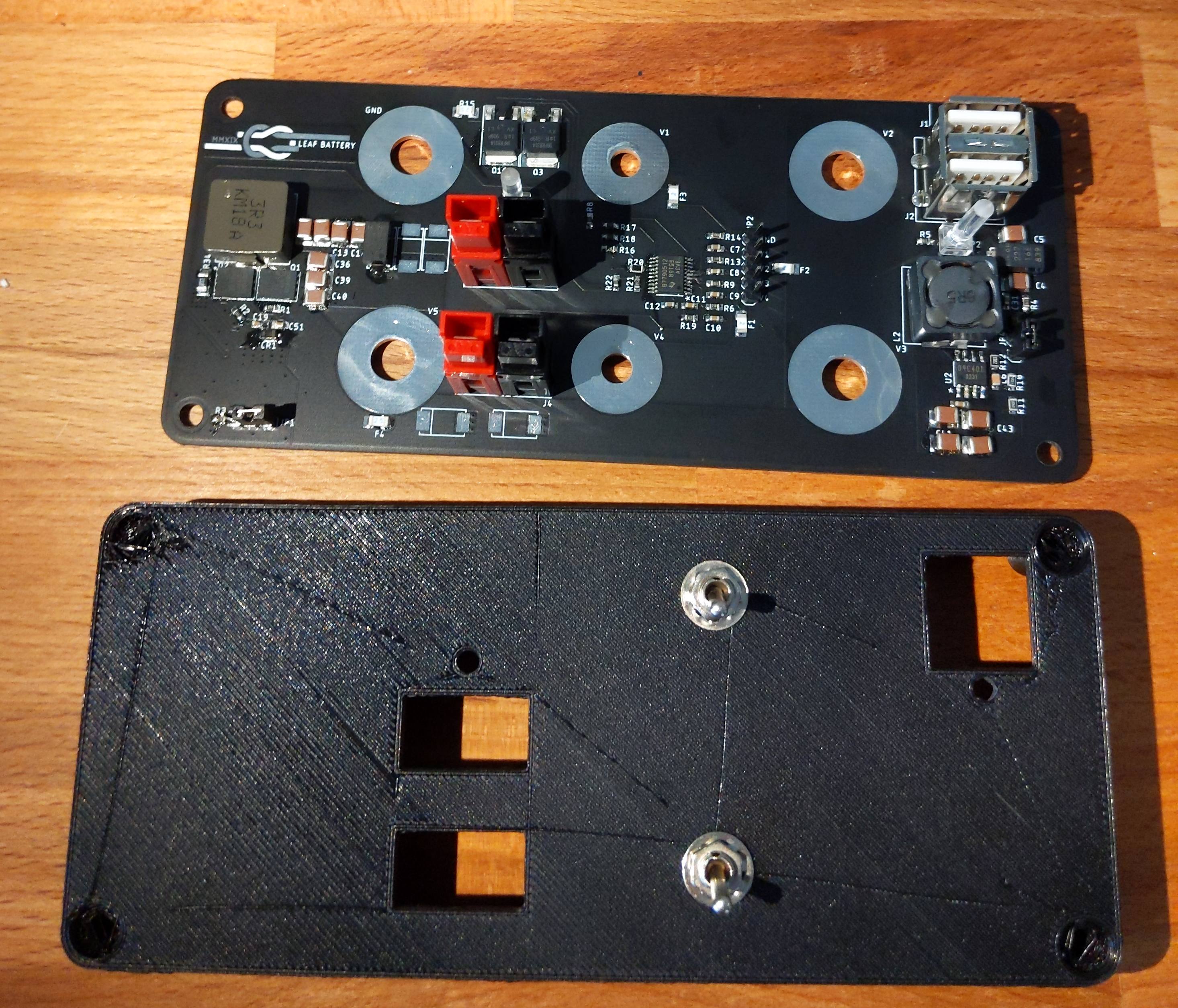
The design of the Nissan Leaf cells also makes it possible to mount a battery protection and power conversion board directly to the cells and avoid having to build any wire harnesses.
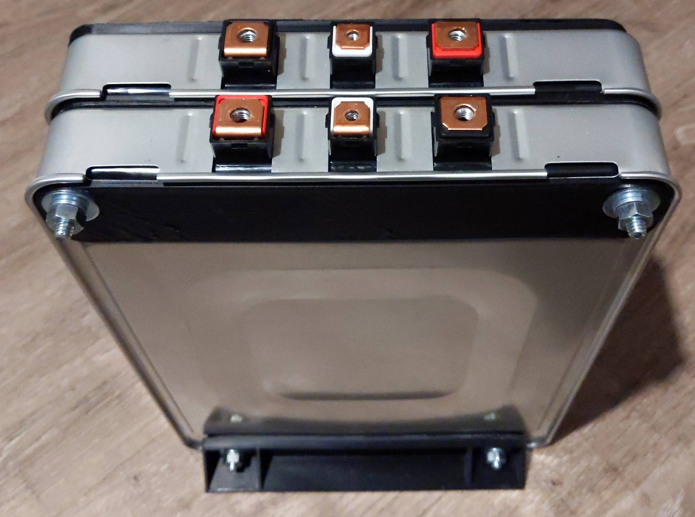
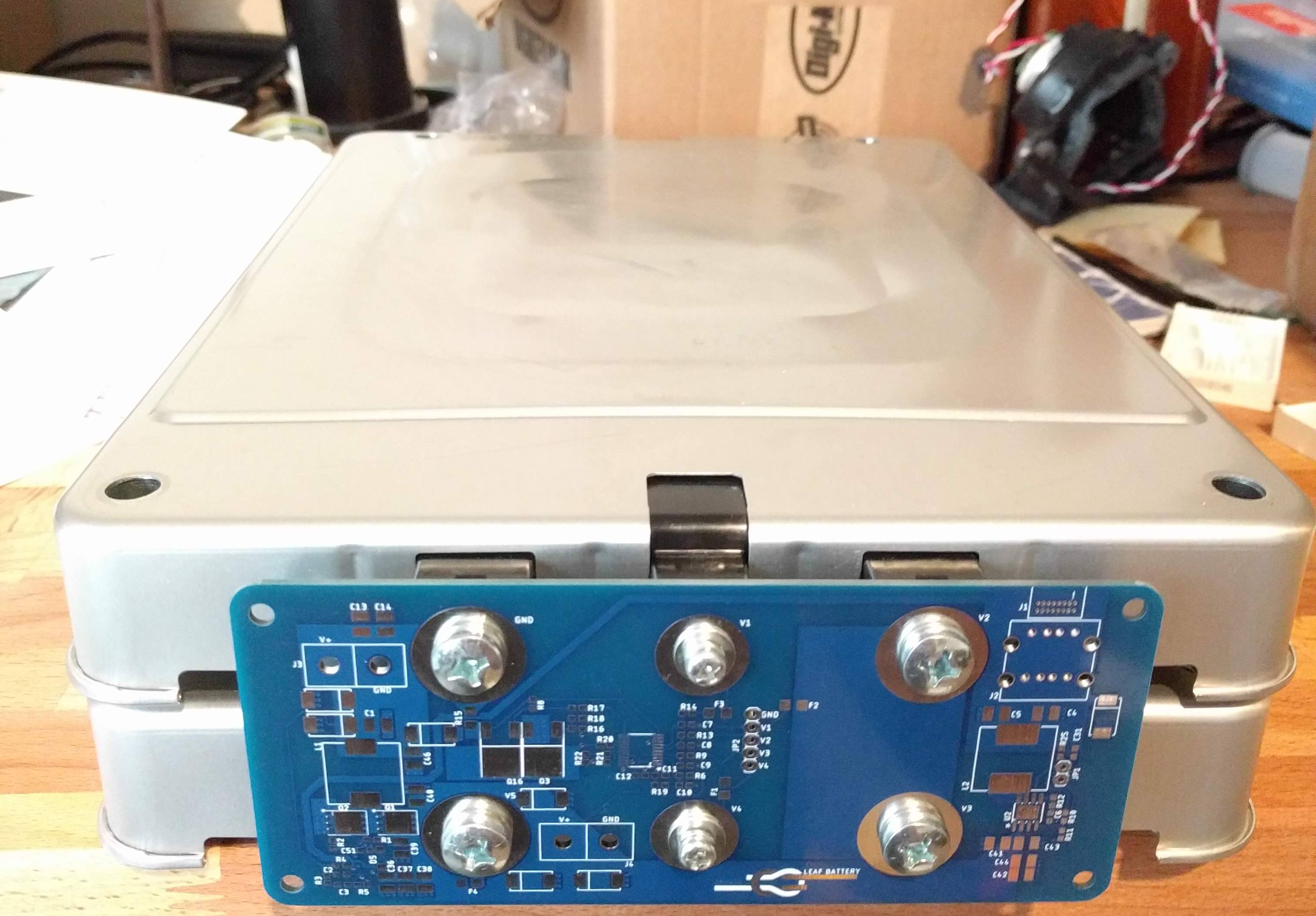
Pack Without Power Board
The top of the cells directly interface to the bottom of the PCB. I added a 'bump' of solder to the bottom of the board to make sure that the battery tabs only made contact where in intended.
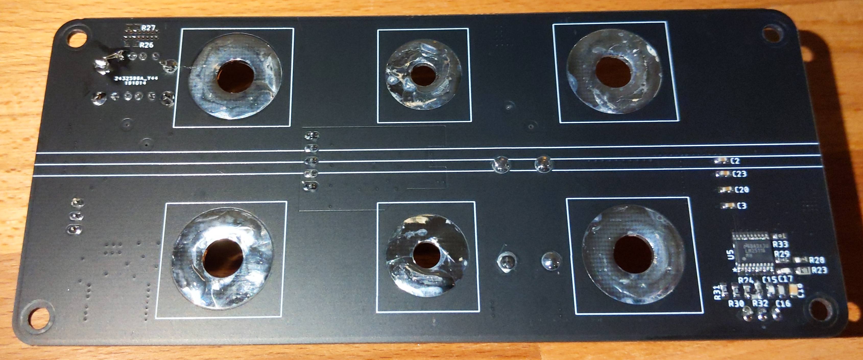
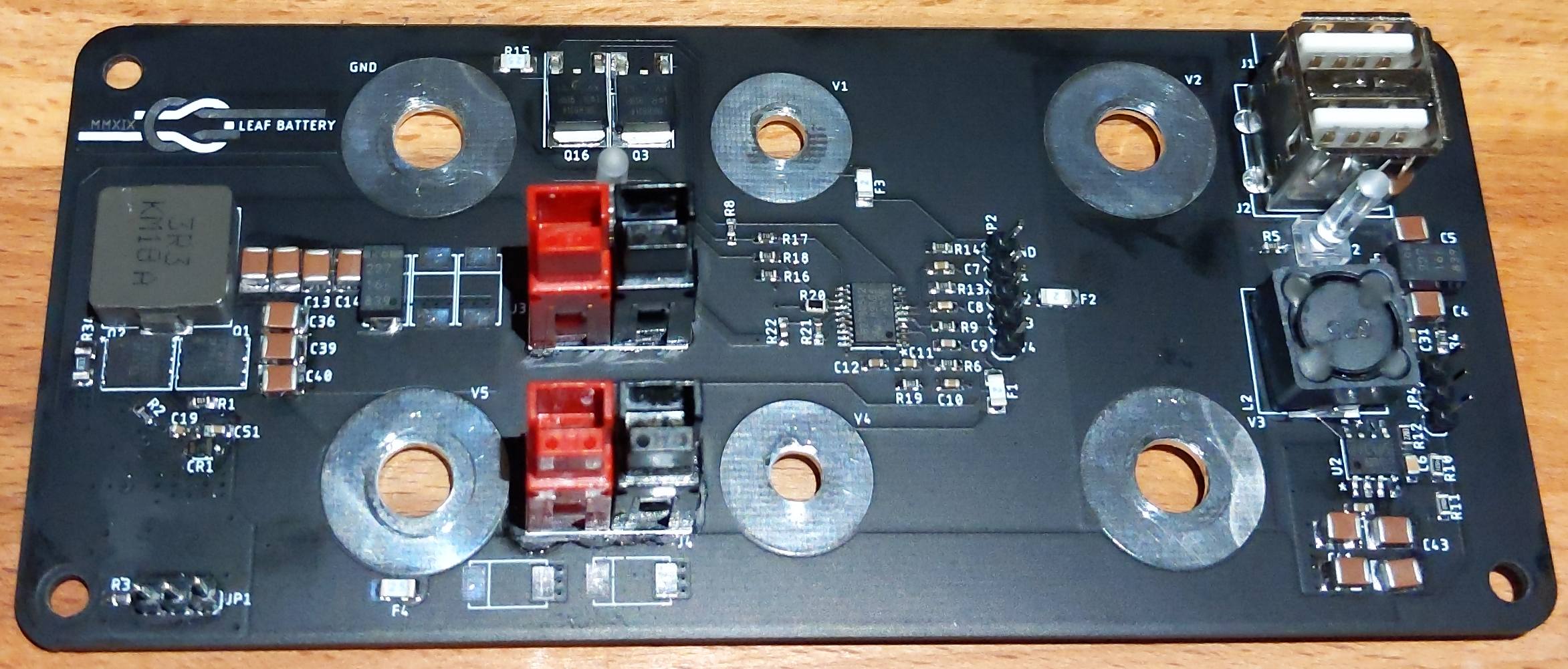
Bottom of Power PCB
Battery Protection
Unlike Lead Acid batteries which can be recovered after total discharge and which can handle being overcharged, lithium ion batteries will be permanently damaged if they are discharged below ~2.5V per cell or charged above ~4.2V per cell. The simplest way to implement this protection is to use an IC designed for this task, and there are a lot of chips that do this (370 results on Digikey). I chose TI's BQ7790512PWR because it is available with a range of cutoff voltages. Often these protection ICs will not kick in until 4.25 or 4.3V on the high end and 2.5V on the low end. They are designed as secondary protection to be used with chargers and loads that will shut off before the hardware limit. I wanted to be a bit more conservative: the low end cut off of this chip is 2.8V and the high end cutoff is 4.175V.
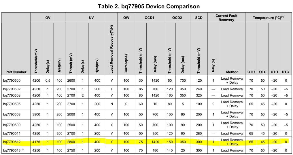
Characteristics of BQ7790512PWR
This chip controls two low side MOSFETS: one allows charging and one allows discharging. When the all the cells of the battery are at a safe voltage (and the thermistor reports a safe temperature), battery voltage is applied to the input of the two buck converters.
The battery protection chip provides over-current protection (though the limit is 70A with the sense resistor value in the schematic at the moment, oops), but for additional protection each of the battery terminals is fused to protect against accidentally short circuiting something on the board. The sense paths have 3A fuses and the power paths have 25A fuses.
Buck Converters
The voltages of lithium ion batteries don't align very well for some devices made to work with lead acid batteries. A six cell lead acid battery is ~10.5V fully discharged and ~14.5V when it is on a fast charger. A 3 cell lithium ion battery is 8V fully discharged and 12.6V fully charged while a 4 cell lithium ion battery is 10.8V fully discharged and 16.8V fully charged.
Circuit Board
My solution was to add a buck converter with a 13.25V output that can be used when the battery voltage is to high for standard 12V devices. The inductor in this buck limits the max current draw to 15A which is enough to run air pumps, ham radios, car chargers, and COTS inverters. Anderson Powerpole 30A connectors are used for both the battery voltage and 12V output.
The 12V buck uses external FETs to handle the current, but the 5V buck only needs to supply 4A, so I used a simple integrated switch buck regulator. Both converters have enable pins which are tied to the switches on the front panel, and each has an LED to indicate whether or not it is on.
First Revision with Faulty 12V Buck
I ended up making two revisions of this board. There were issues with the layout of the controller I originally selected for the 12V buck, so I rev'd the board with a better chip, better power layout, and an improved placement of the Andersons.
Mechanical Parts
These batteries are designed to be bolted together with spacers in between the batteries and plates on the end. Instead of buying the original hardware, I 3D printed my own. There are five different prints:
- 2x Legs
- 2x Bottom Spacer
- 3x Top spacer
- 1x Bottom Cover
- 1x Top Cover
The legs and spacers are clamped together using 3.4" long "1/4-20 bolts with washers and nuts. 6-32 nuts are inset into the bottom PCB cover and then the top cover is screwed on using 1.5" long machine screws. The bottom cover prevents anything from shorting out the contacts from the bottom side of the board which makes it safe to throw the pack in a backpack.
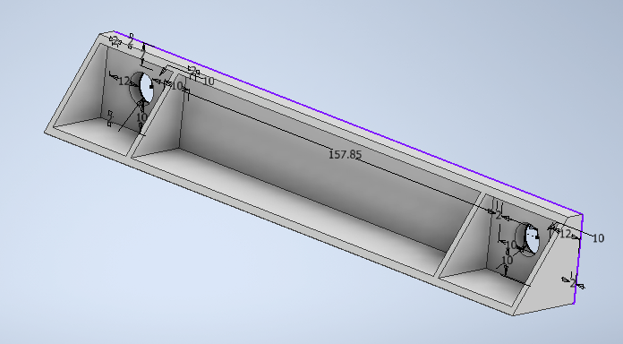
Leg 3D Model
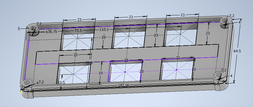
Bottom PCB Cover Model
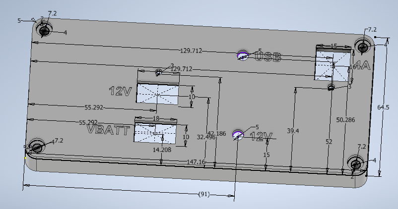
Top PCB Cover Model
The top cover is sized to line up with the top of the USB connector, and the light from the LEDs is brought to the top using appropriately sized light pipes.
Top PCB Cover
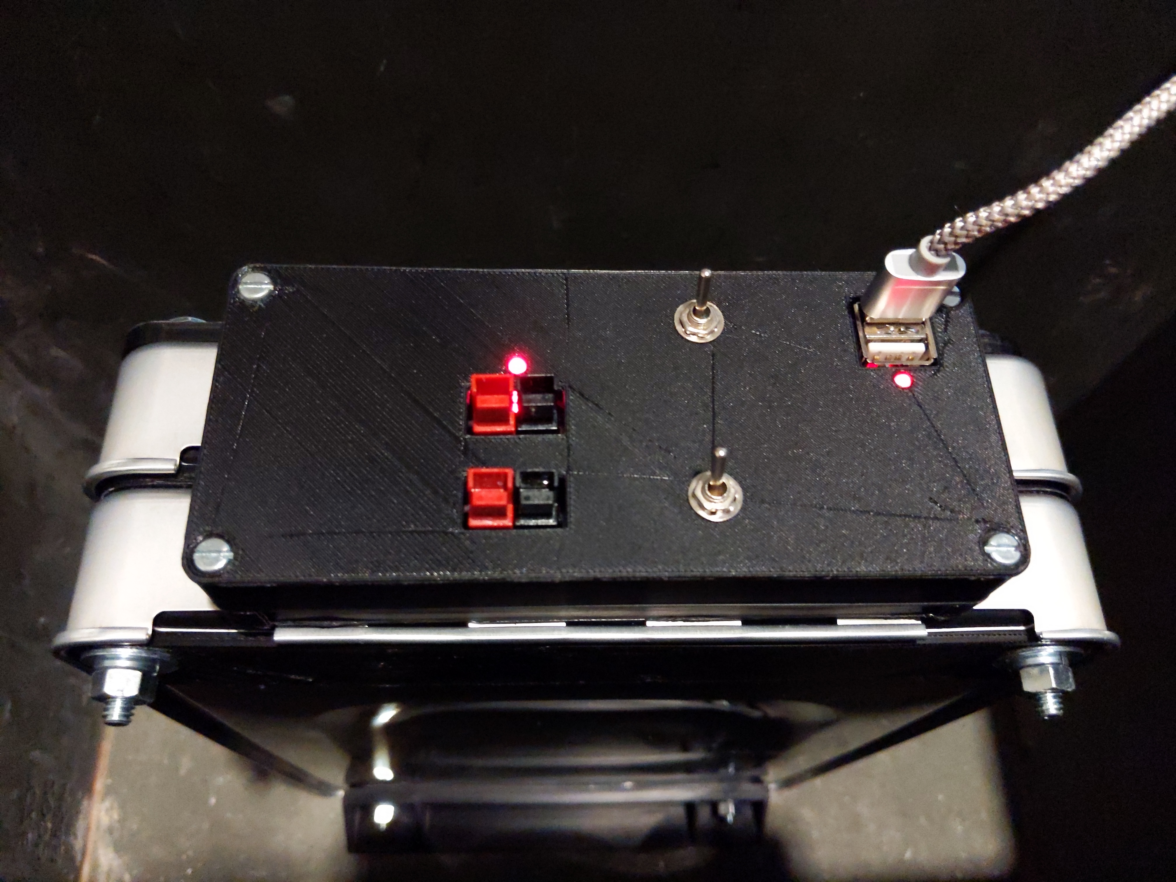
Finished Pack