Vape ASIC
2022
There are some interesting ASICs (application specific integrated circuits) in mass market projects. PT8A2514, for example, is a toaster timing and control IC that has a 'bagel' pin. So many toasters are made per year that there is room in the market for multiple manufacturers of drop in compatible toaster control ICs (mostly no-name Chinese companies: Siyom, AnteceDesign, China Microelectronics, but also Diodes Inc. due to their acquisition of Pericom). You could achieve all of the functionality of this toaster controller using a a few flip flops and 555 timers, but that will cost more than a dedicated controller. With disposable vape sales in the United States totaling 8 million between March 2020 and March 2021, there's sufficient volume to justify the $100k-300k cost of developing a custom ASIC.
S085 Vape ASIC
There is no datasheet for this IC (S085), but the application circuit (identical to circuit in the vape I took apart) can be found in US patent 2017/0215484. The initial patent application was filed in 2014, so this part is at least eight years old. I was speculating with a friend (neither of us use the things) how the drive circuitry in vapes was likely constructed, so I decided to hook one up on my bench and see how it behaved. We predicted going in (before seeing any of the innards) that vapes likely switch current to the coil with a low side N-channel MOSFET and that the control IC PWMs the heating coil to compensate for changes in battery voltage. Both predictions proved to be wrong.
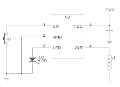
IC Pin-out and Reference Circuit from US patent 2017/0215484
Ignoring the fact that flavored vapes with varieties like "Strawberry Ice Cream" and "Mixed Berries" seem to be designed to appeal to children, these devices are a terrible waste of materials. The only thing consumed is the e-liquid and battery charge, so if there were a way to charge the battery and refill the liquid, a single device could be reused many times. That's right: Each of these contain a rechargeable 1000 mAh Lithium Ion cell that is used only once before going to the landfill. I might make a simple USB charge bank board to take advantage of the pile of extracted cells that a friend has accumulated. I lost my old charge bank, so making a new one out of recycled e-cigarette cells seems like the right course of action.

Definitely Not Designed to Appeal to Children
Part Specifications
I could not find a source of the loose IC anywhere online, but I could find a source for the assembled button shaped module that integrates the IC on a circuit board with a pressure sensitive switch, a bypass cap, and an LED. Here is the poorly translated marketing text:
With ASIC design, it prevents the halt that happens in the current MCU design, and also avoids not being able to reset when the IC is under threshold voltage. The IC works stably, and also provides protection when heating coil is short, the IC can turn off when load resistance is below 1ohm; At power-down mode the IC achieves a quiescent current under 3uA. The output current exceeds 1A during smoking; At the same time, the S085 offers visual LED working mode instructions, which shows different LED indication when the IC is working under different modes¬ Including start up, smoking, voltage detection, short circuit protection, charging. The IC achieves excellent charging performance, S085 provides complete battery protection; Build in charging control circuit, support AC adapter, USB and other charging devices. The IC is trickle charge mode when lithium battery voltage is under 2.7V which protects the battery. When battery voltage exceeds 2.7V, it turns into large charge current mode, then the charging current starts to drop when the battery voltage approaches 4.2V. The detection error is kept within 1%. The S085 integrates a regulator to reduce the loss. The IC is available in SOT 23-5 package. The small volume and the use of the least passive components (a LED and a capacitor) achieve the overall solution cost.
Features:
- ASIC Design
- Low quiescent current(< 3uA)at power-down mode
- Build in short circuit protection (SCP)
- Build in 3.1V under voltage protection (UVLO)
- Build in over temperature protection (OTP)
- LED working mode instruction
- High voltage detection accuracy (within1%)
- Complete battery protection
- Low quiescent current (< 3uA)
I think the references to charging are not applicable to this IC and instead may apply to the other IC shown in figure 3 of the patent, but I confirmed through test that the part did implement the rest of the claimed features aside from "high voltage detection accuracy." I measured a UVLO (with a light load) of 3.25V which is definitely more than 1% higher than 3.1V, but it could be that the nominal UVLO setpoint is actually 3.25V.
Part Behavior
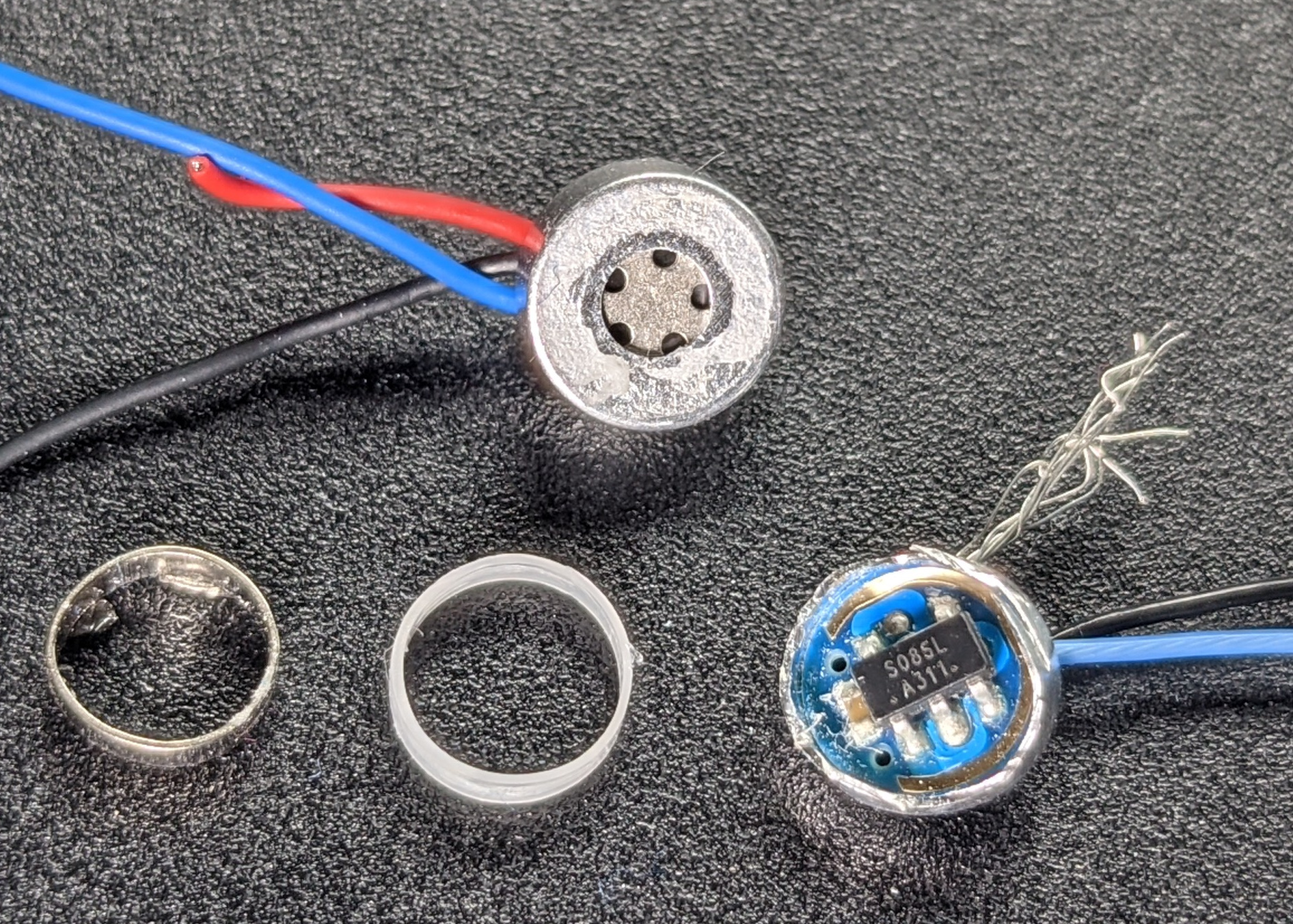
Before talking about the behavior of the IC itself, I need to talk about the little button it is packaged in. This button is on the bottom of the vape and acts as a pressure sensitive switch. When a user sucks on the top of the vape, pressure inside drops due to small holes that constrict air from flowing in freely. The button has its own air hole at the bottom of the silicone body of the vape, so the full pressure difference between outside and inside is applied across it. Inside the button, there is an insulating plastic ring with a metal ring covered in a metalized film on top of it. When pressure inside the vape drops, outside air pressure pushes this film into contact with the top cap of the button closing the input switch circuit.
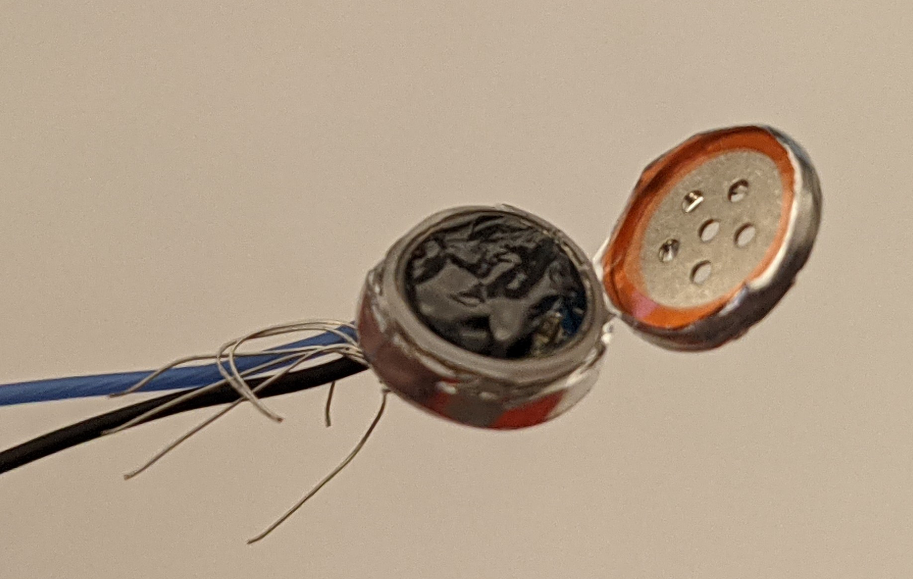
Pressure Switch Conductive Membrane
There are two non-plated holes though the circuit board inside the button that allow the inside of the can to stay at the same pressure as the outside of the vape.

Bottom of Button PCB (Side Facing Bottom of Vape)
What isn't pictured is the felt piece that covered the top of the button (the side facing the inside of the vape). This is there presumably to absorb any errant e-liquid so that it doesn't gum up the pressure switch.
Pressure Switch Internal Components (Conductive Film Removed)
Normal Operation
I was surprised by how the high current and LED outputs were implemented. The heating coil is switched on the high side which implies that a P-channel MOSFET was used rather than a cheaper N-channel MOSFET, and coutput does not seem to be regulated beyond applying a current limit. The LED output, which slowly increases brightness when the part is enabled and slowly dims after the part turns off, appears to be implemented linearly rather than by PWM.
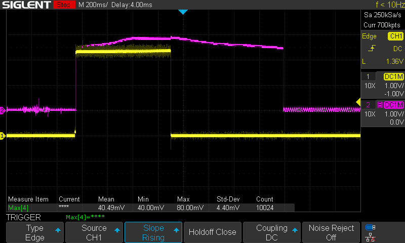
LED Voltage (Pink) and Output Voltage (Yellow) During a Normal 'Puff'
The IC applies a very quick test pulse to the high current output to presumably see if it is driving into a short circuit. There is then applies a limited current for 7.7ms (possibly to further make sure it isn't driving into a short circuit) and then applies full voltage.

Turn-on Test Pulse and Test Current
The test pulse is quite brief: around 200ns.
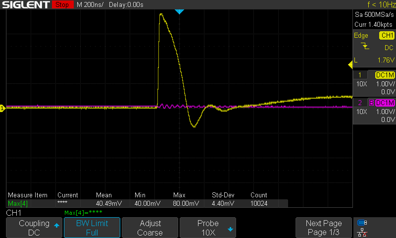
Turn-on Test Pulse Detail
With a lighter load, there is (unsurprisingly) a higher output voltage during the test current plateau:

Turn-on Test Pulse Detail
Abnormal Operation
With a very light load, the output is pulsed, but the LED does not indicate that there is an error condition.

Open Load Behavior
The output times out after ten seconds of operation which protects against pressure switches failing closed. The LED is then flashed twice to indicate the error.
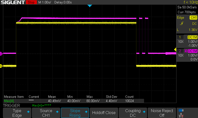
10 Second On-time Timeout
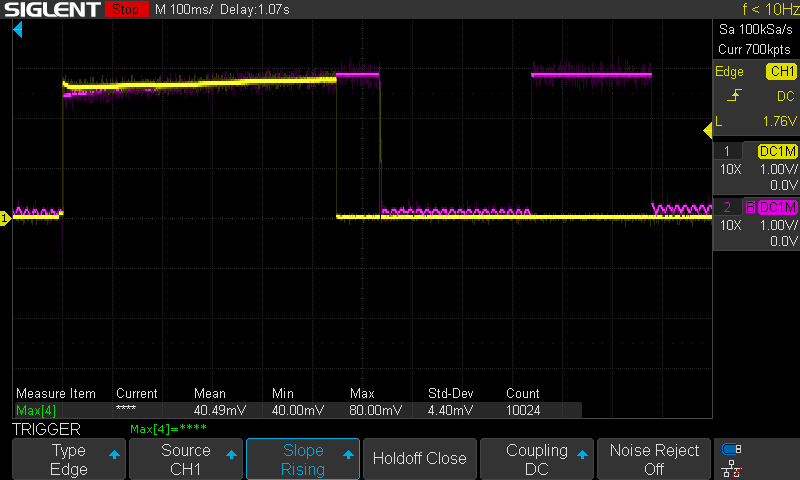
The part seems pretty will protected. With moderate current for a long enough period of time, the part applies a low frequency PWM to the output for what seems to be thermal limiting. This was induced by running the part for several consecutive 10 second cycles to warm it up sufficiently.

Suspected Over-temperature Duty Cycle Limiting
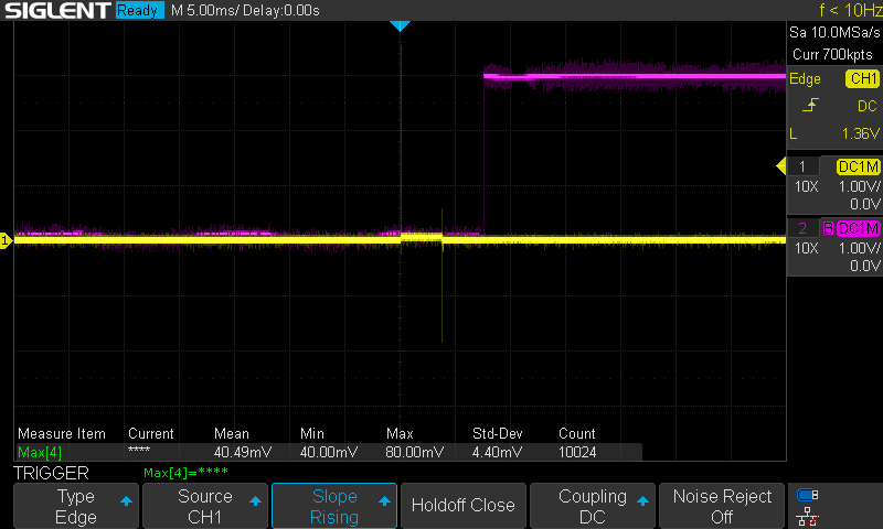
The part will terminate output early if the current is slightly too high.
Overcurrent Output Termination and LED Error Pulse
With a severe overcurrent / short circuit, the part will not make it past the test pulse and test current step.
Short Circuit Test Pulse and LED response
The part does enforce a pretty aggressive under-voltage lockout. The marketing description I found online indicates a UVLO of 3.1V, but the unit I tested activated its UVLO circuit at 3.25V, so more than 20% of the cell's capacity is not utilized. Batteries in 'dead' vapes should maintain a safe charge level (above 2.8V) for a year or three.
Test Setup
I ran the circuit off of a bench power supply and triggered the circuit by shorting the inner ring on the PCB to the outer case with tweezers as the conductive film would in the pressure switch. For a variable load, I used a length of solder. To adjust the resistance, I varied the distance between the alligator clips.
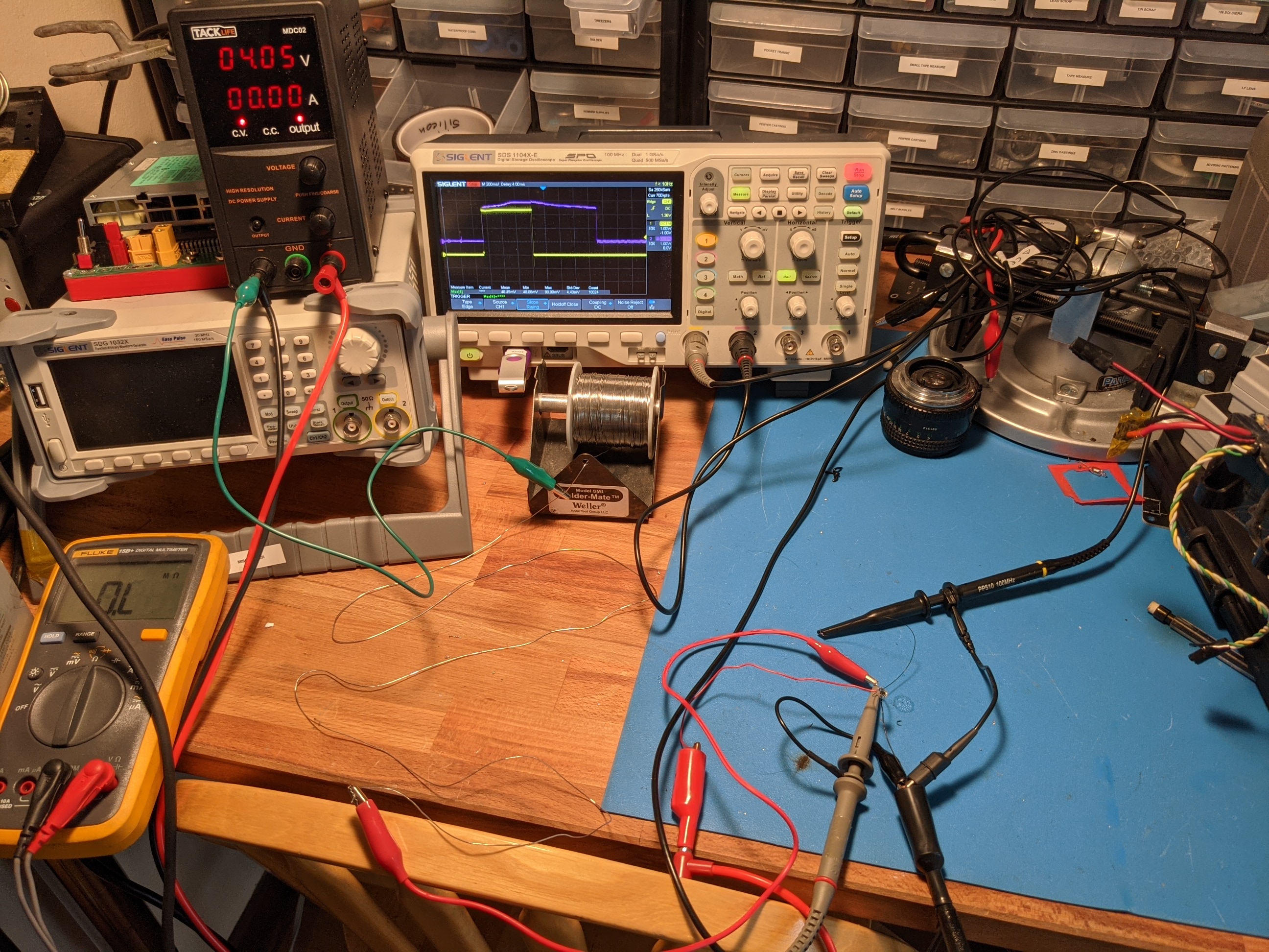
Test Setup