Questionable Idea: Improved Candle
2023
Candles are terribly inefficient. A typical candle puts off around 13 lumens of light and 80W of heat which is (ignoring the negligible energy of the light) an efficiency of 0.16 lumens per Watt. High efficiency white LEDs now have efficiencies above 220 lumens per watt, so by converting the heat output of the candle into electricity with a thermoelectric generator to power an LED, you can increase the light output of a candle significantly. Even if only 50% of the heat is captured and the efficiency of the thermoelectric generator is only 2%, you should be able to increase the light output of the candle by a factor of ten. This is a silly project, but it does work; I can effectively read and work by the light of my improved candle.
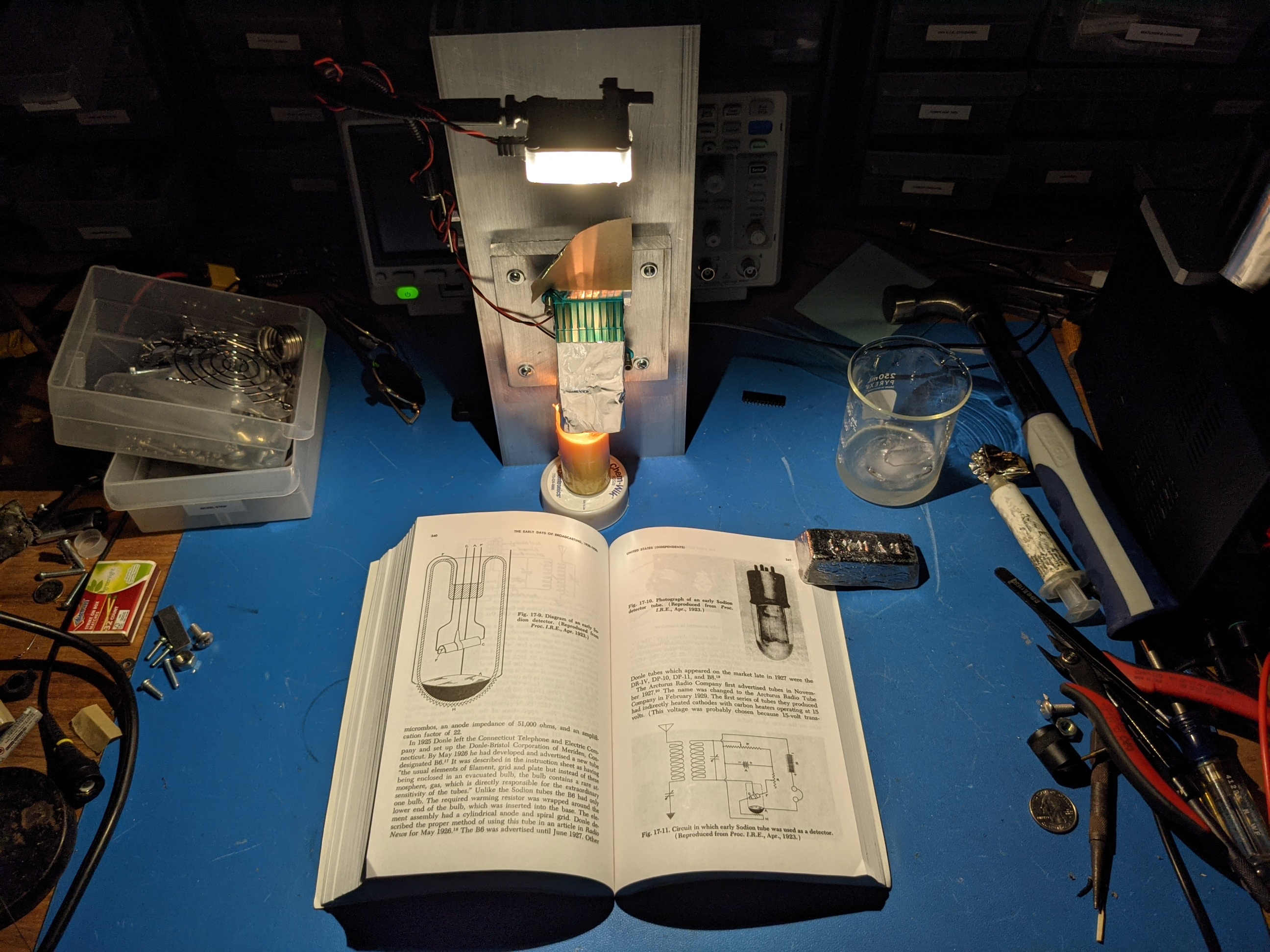
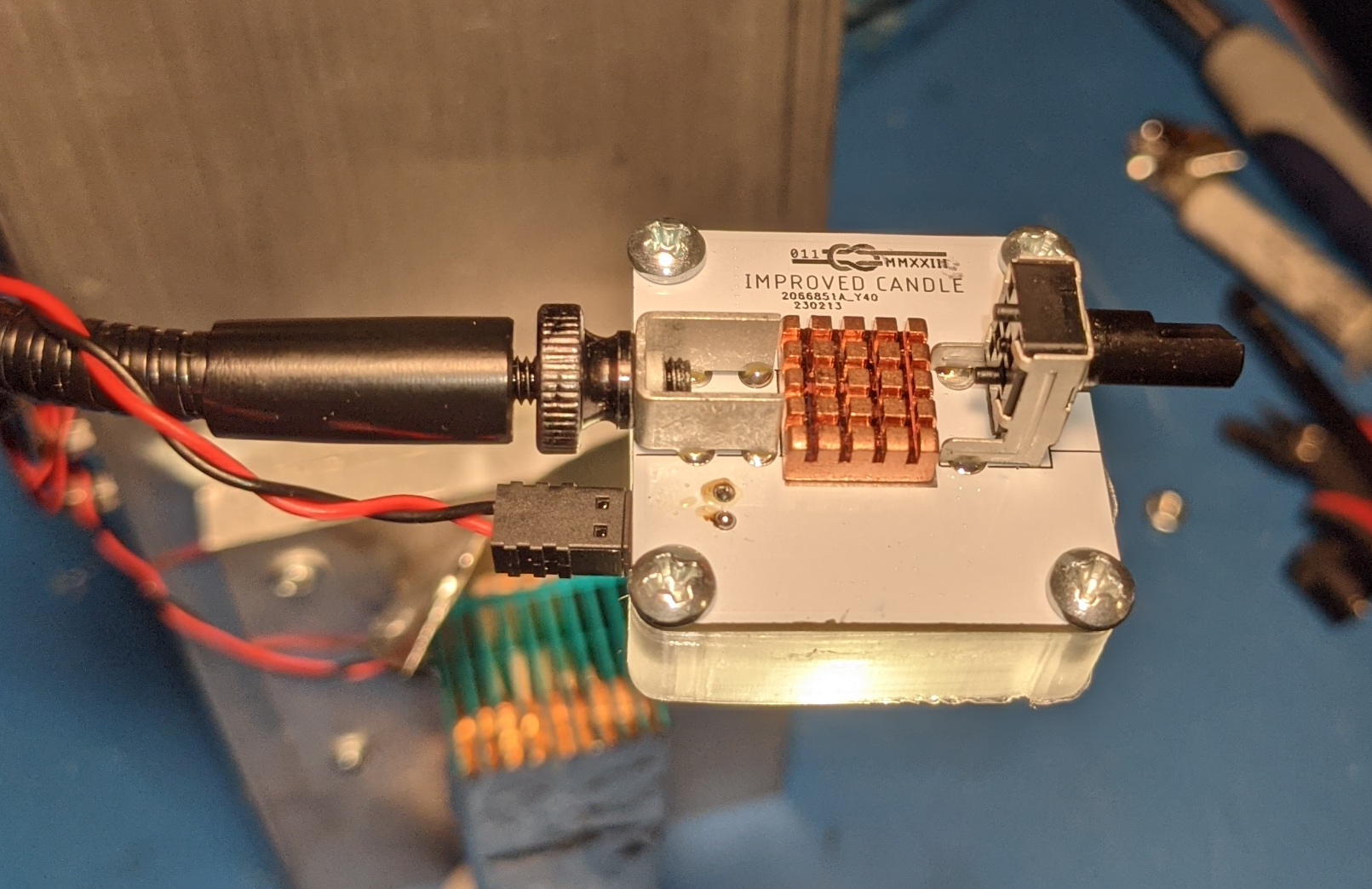
Reading by the light of the Improved Candle
Overview of Why This is a Questionable Idea:
- Thermoelectric generators are very inefficient.
-
- With a 270C temperature difference between the hot and cold side, you can expect ~4.5% efficiency.
- With lower temperature differences, efficiency drops.
- With a beeswax candle, I achieved a ~45C temperature difference which results in perhaps 1.5% thermal to electrical efficiency.
- Relatively expensive hardware is required to dissipate heat without a fan.
-
- $40: One 5x12x1.75" Wakefield-Vette 125397 heatsink for the cold sink.
- $15: One 4x4x0.5" aluminum plate to provide setback from the main heatsink and to spread heat.
- $6: Two titanium 6-32 screws.
- $6: One 40x40x35mm ATS-CPX040040035-158-C1-R0 hot side heatsink.
- $11: One 30x30mm TEG1-1263-4.3 Thermoelectric Generator.
- $6: One 12" Gooseneck arm.
- $4: Various hardware and screws.
- $15: Parts and PCB for the LED board.
- Total: $116.
- You would probably be better off buying a battery bank and a solar panel.
-
- All of the top solar power banks on Amazon are probably scams.
- The top eight results on Amazon claim at least 27Ah, but given their size are quite unlikely to have a capacity above 16 Ah.
- Assuming the 1.9W solar rating is accurate, five hours of charging will give you the enough energy to run a light with more power than the improved candle for 24 hours.
- The most practical use-case for the improved candle is for power in a basement during a storm (if your batteries died) or a nuclear winter.
-
- 100 packs of 4-hour tealight candles can be bought from Walmart for $0.05 each.
- That will provide 16+ days of continuous light for a cost of $0.30 per day.
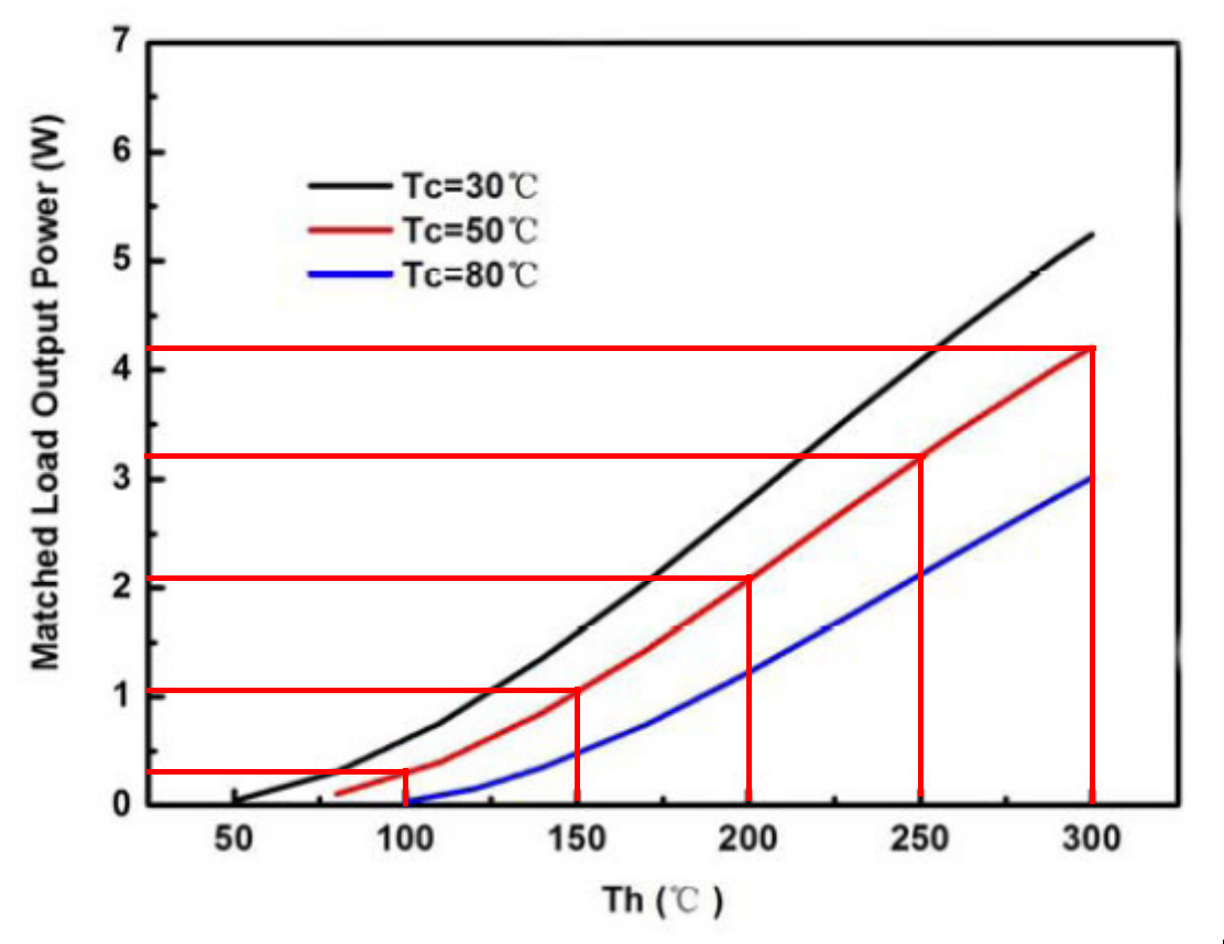
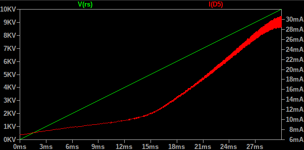
TEG Power vs. Temperature: Power is Very Low with a Low Temperature Delta
Design
There's two parts to this project: the mechanical bits and the LED driver. I came across some cheap high temperature thermoelectric generator (TEG) units on eBay a couple years ago and bought them for later use — I didn't have this particular project in mind at the time, but I had been interested in building something to use waste heat charge a power bank.
Mechanical Bits
Since I didn't want to waste what little power was available from the thermoelectric generator (TEG) running a fan, I had to use a large heatsink for the cold sink. I selected Wakefield-Vette 125397 since it offered the lowest thermal resistance to ambient for a reasonably priced heatsink. Since the TEG is much smaller than this heatsink, I added a 4x4x0.5" aluminum plate as both a heat spreader and to allow the candle to sit further away from the cold plate. For the hot side heatsink (the one that captures heat coming off the candle), I chose a heatsink with closely spaced fins that was slightly larger than the TEG; I selected the option with the longest fins available that met this criteria: ATS-CPX040040035-158-C1-R0.
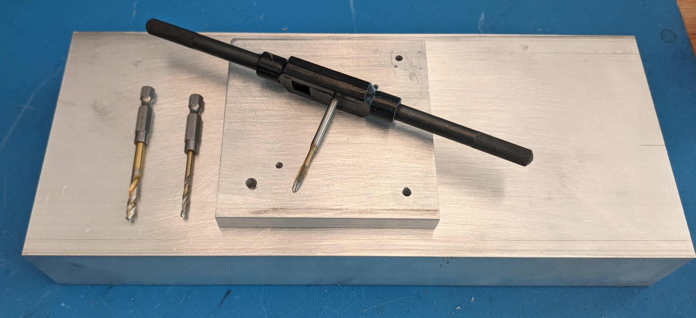
Drilling and Tapping Cold Heatsink and Heat Spreader
All of these pieces are connected together with 6-32 screws. The heat spreader plate is bolted to the cold heatsink (with thermal compound in between) and the hot side heatsink compresses the TEG between the heat spreader and itself with springs on titanium 6-32 screws. Since these screws are a direct leakage path from the hot side to the cold size, I used titanium since its thermal conductivity is 1/4 that of steel and 1/20 that of aluminum. I drilled all of these holes with a cordless drill and tapped the holes by hand.
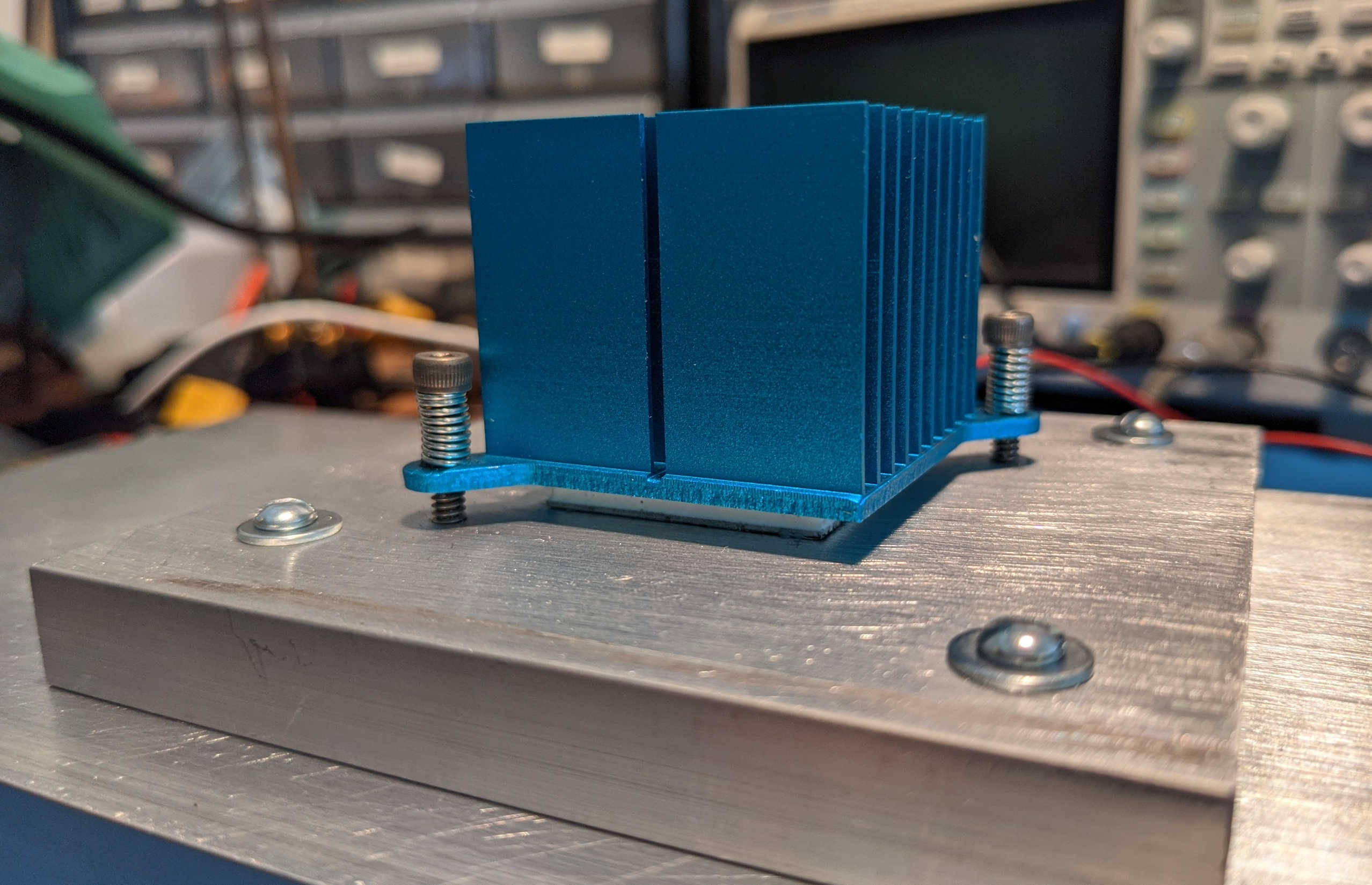
Heatsink Compression
The TEG itself has a dry graphite thermal interface material, so I did not apply any thermal compound to it and instead just ensured that it was clamped evenly using some springs that I found at a hardware store. The spring was longer than I needed, but I couldn't find any pliers in my apartment that were able to cut it. I thought about other options for a minute and then realized I could just melt it in half using my spot welder. After a couple tries at increasing pulse durations, I melted it clean in half.
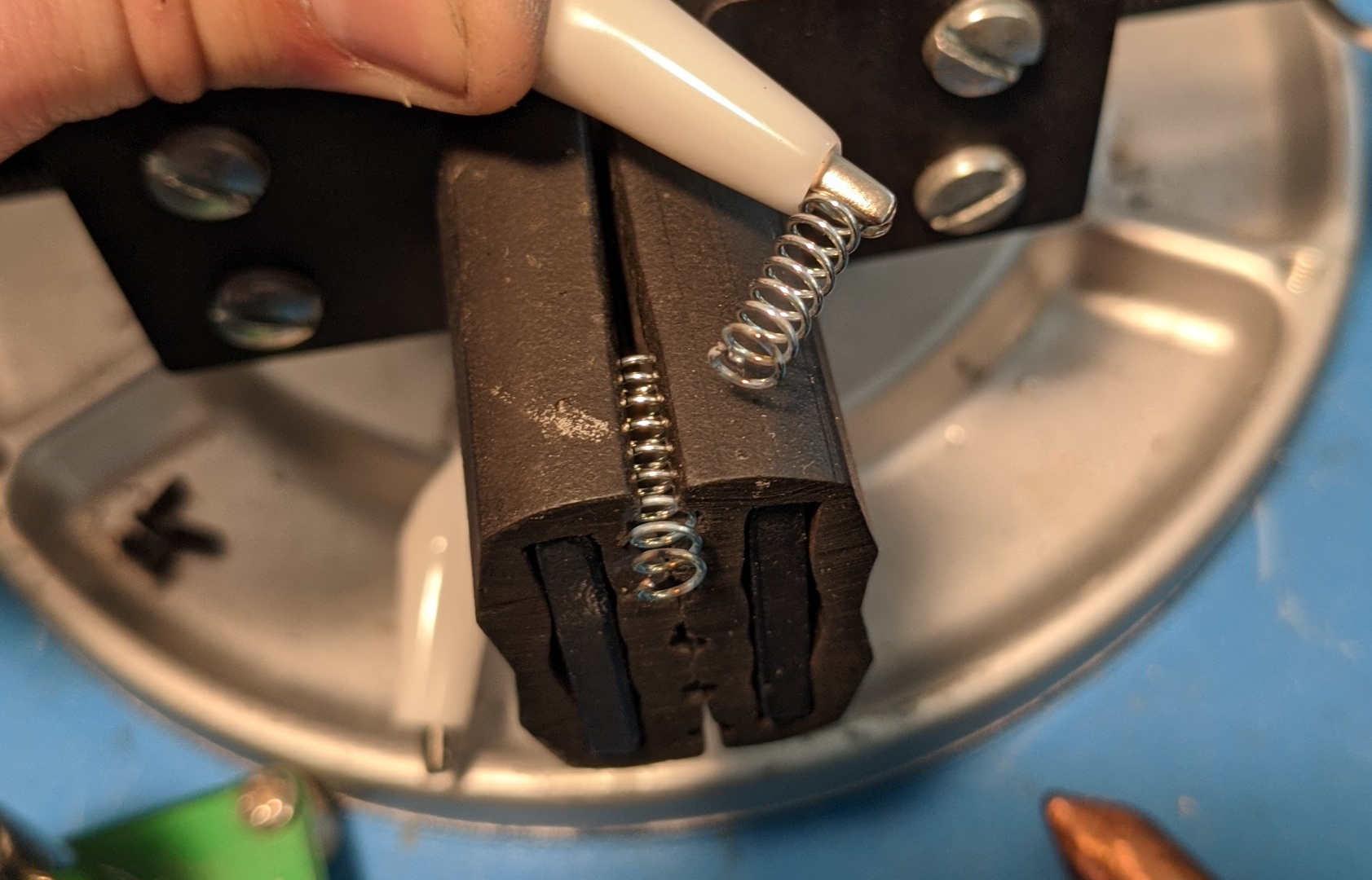
Spring Cut with Capacitive Discharge Spot Welder
The other half of the mechanical assembly is the arm that holds the LED board. I found a cheap gooseneck arm on Amazon with a #10-24 screw base and a M4 stud on the other end. The #10-24 end is connected to the heatsink with a right angle bracket sitting on short #6-32 standoffs. The LED board is connected to the arm with a through hole right angle screw terminal.
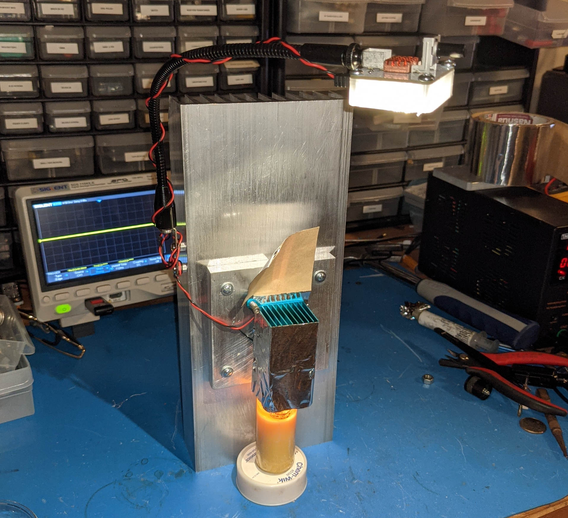
Gooseneck Arm Holding LED Board Connected to Heatsink
The last mechanical piece is the light diffuser for the LED board. I designed this in Onshape using a dxf export of the board outline and screw locations and then printed it in transparent PETG. I slightly undersized the holes in the diffuser and then drilled and tapped them for #6-32 screws. I used aluminum tape to direct hot air off the candle through the hot side heatsink and to feflect exhaust air away from the cold heatsink.
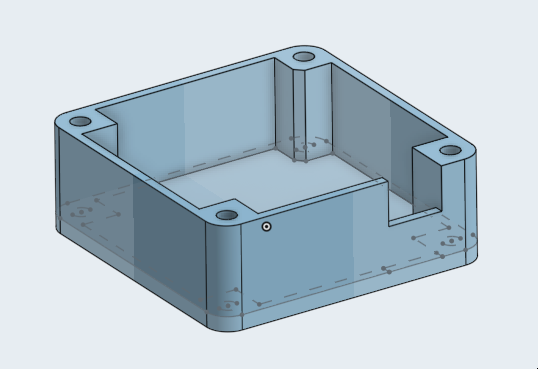
3D Model of Diffuser
LED Driver
To get the most power possible out of a TEG, you have to present it with a load matched to its operating conditions. This can be done with a maximum power point tracking algorithm like you would with a solar panel. You can also play tricks with the fact that the maximum power point for a TEG will be at a voltage equal to half its open circuit voltage (or at a current half that of the short circuit current). Rather than do that automatically, the user of the Improved Candle maximizes the power into the LED by adjusting a potentiometer that controls the duty cycle of a boost converter. In practice, with only a candle (and not a higher power input like an alcohol burner) the counterclockwise most position of the potentiometer will be quite close to optimal.
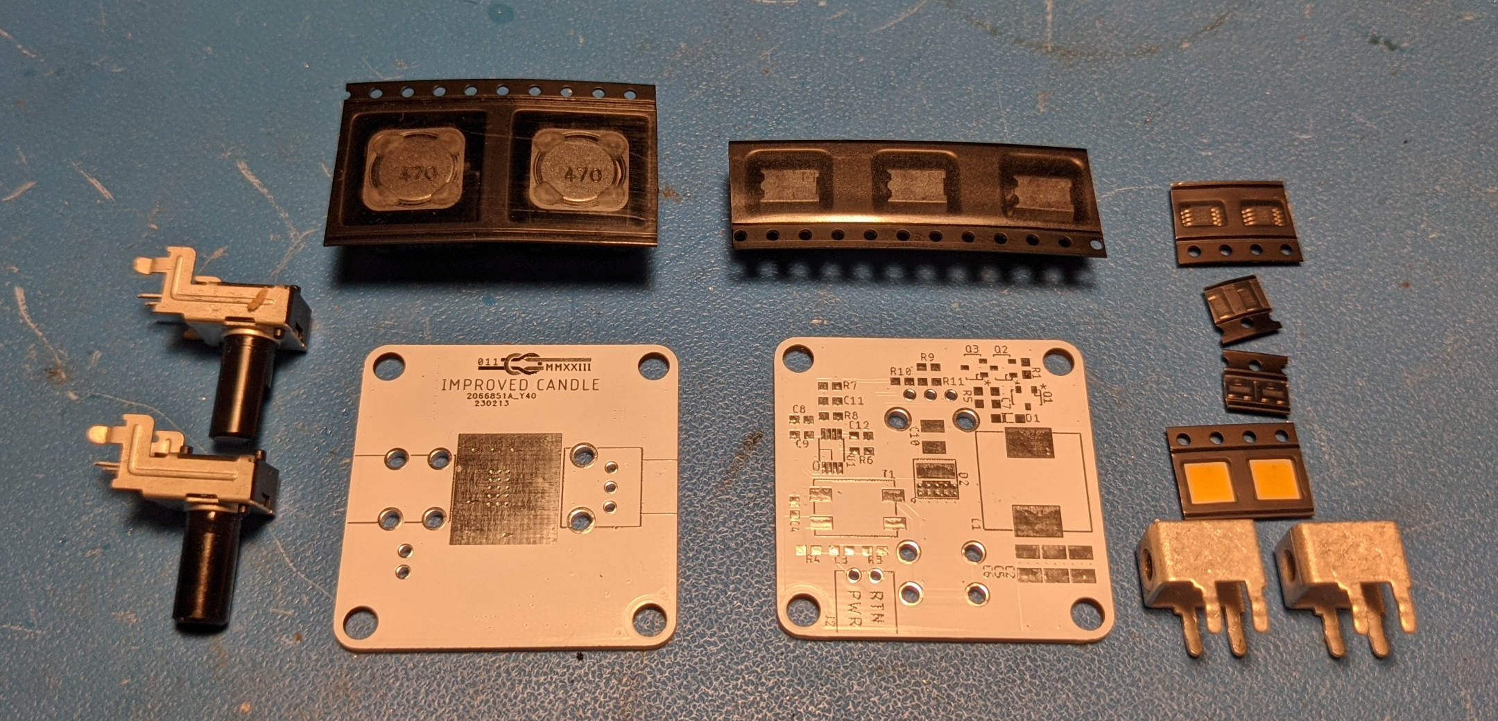
Major Parts of the LED Driver Board
The LED driver consists of a boost converter with a 555 timer acting as a variable duty cycle PWM generator and a totem pole gate driver:
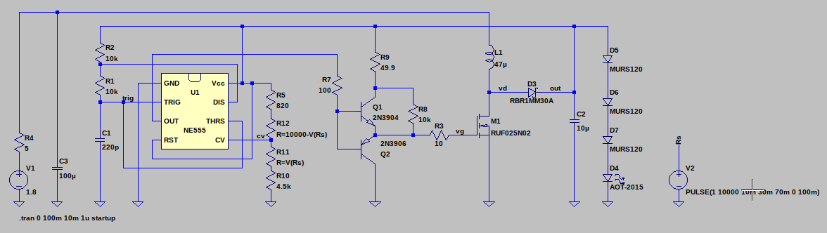
LED Driver Schematic
Due to the low output voltage of the TEG with just a candle as an input, I had to be careful with the parts selection for the 555 timer and the MOSFET and diode in the power stage of the boost converter. I needed a high speed (>1MHz) 555 timer with a reasonable output current rating and low operating voltage 555 timer. LMC555CMM/NOPB fit the bill. For the MOSFET, I needed a part with a very low threshold voltage and reasonable current carrying capability with low switching losses. For that, I selected BSS806NEH6327XTSA1 which has a threshold voltage of 750mA and an on resistance of 57mΩ at 2.5V. For the diode, I selected CRS01(TE85L,Q,M) which has a forward voltage drop of only 0.36V at 1A.
Note that this circuit is entirely open loop: there is no feedback to control output voltage. The LED this circuit drives effectively acts as a shunt voltage regulator: it starts drawing current at around 5 V and will draw 1 A at 6.5V. This means that the output voltage of the boost converter will fall somewhere in the range of 5V and 6.5V for any possible output of the TEG which has a maximum power output of around 5W.
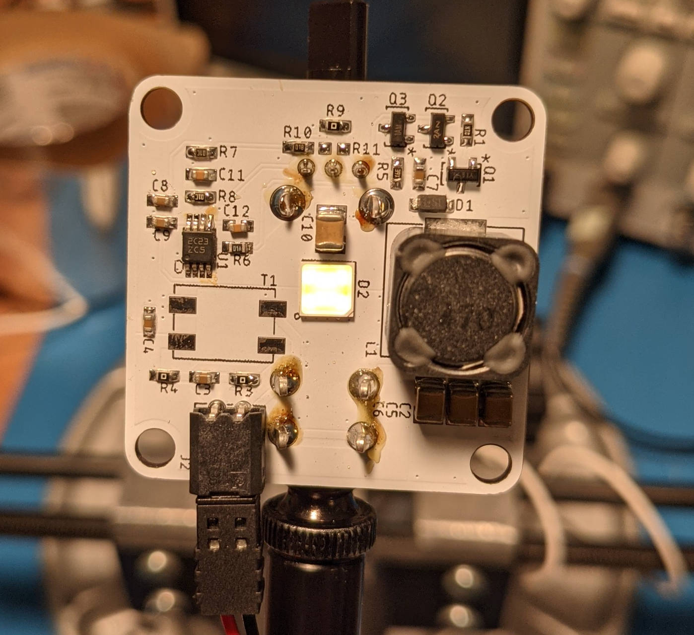
Bottom of LED Driver Board
The LED driver board is a normal two layer PCB form JLC PCB with white soldermask and leaded HASL finish. I used white so that it would reflect stray light down rather than absorb it. I added a copper heatsink held on with an adhesive pad on top of the LED, but at typical power levels this is totally unnecessary. The LED itself is the highest efficiency — or to use industry terminology, luminous efficacy which takes the sensitivity of the human eye into account— (224 lumen/W) warm white (3500 K) LED available on Digikey: GW Q9LR33.PM-M4N3-XX56-1-180-R18 from OSRAM. Warm white LEDs have made tremendous progress in the last decade. In 2011, the record from OSRAM was only 142 lumen/W and the first commercially available white LED back in 1996 had an luminous efficacy of only 5 lm/W.
Top of LED Driver Board
Cold white LEDs have higher efficiency than warm white LEDs, but that would ruin the ascetics of the Improved Candle. The human eye is most sensitive to green light so you would expect that a monochromatic 550 nm light source would have the highest luminous efficacy, but there isn't a much of a market for high power high efficiency high power green LEDs. Cree has a 236 lm/W 'lime' LED, but that isn't particularly impressive improvement beyond phosphor white LEDs.
Circuit Operation
555 timers have been around since before people kew how to draw reasonable schematics. Many example circuits online show only the pin numbers and not pin names of the timer which require you to cross-reference the datasheet to understand what is going on. Beyond that, you'll also find a lot of rather odd 555 timer circuits that seem to have been copied and pasted until all understanding of why they were designed as they are has been lost. For example, the main example for a 555 timer based PWM generator you'll find when you search for one does not have a fixed output frequency. Instead of adding diodes and messing with the trigger input, I just varied the control voltage input. There may be some issue with this which is problematic when generalized outside of my general application, but it is working fine for me here.
Since the output current of the 555 timer is limited, I buffered it with a NPN + PNP totem pole driver. Here is the simulated gate and drain voltage of the low side mosfet as well as the trigger voltage of the 555 timer:
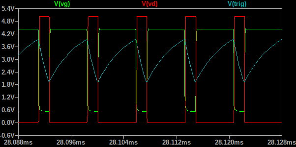
LED Driver Simulation
The potentiometer adjusts the control voltage of the 555 timer which changes the duty cycle. I adjusted the values of the additional resistors to bound the potentiometer such that you can't turn the duty cycle so low that the circuit turns off (and requires a higher thermal delta to restart) and to limit the maximum duty cycle to a bit under 95%. The effect of varied potentiometer position is a bit muddied by transient simulation, but you can see the general trend:
LED Driver Simulation with Varying Potentiometer Setting
Simulation matched reality pretty closely:
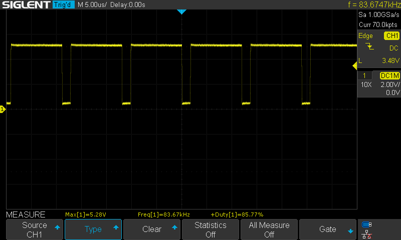
Measured Gate Waveform of LED Driver
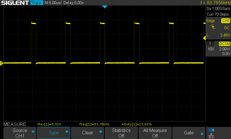
Measured Drain Waveform of LED Driver
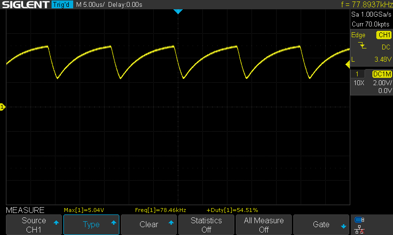
Measured Control Voltage Waveform of LED Driver
Operation
The only trick to operating the improved candle is that it takes a minimum temperature differential across the TEG to get the circuit to start. With lower output power heat sources, this means that you need to add some extra heat to get the circuit to start up. This can be provided with a few matches or by holding a lighter under the hot side heatsink.
Future Improvements
Efficiency of a TEG is a function on the temperature delta across the TEG. This means that an oversized TEG (one that has a thermal resistance low enough that the maximum temperature difference is limited) will be less efficient than an appropriately sized TEG. The TEG I chose for this project is oversized — it would be more suited for use with a higher power thermal input like a bunsen burner or alcohol burner. That was partly intentional: at some point I'd like to build a small gravity fed alcohol burner to use this setup to run higher power loads or charge batteries.
Tea light candles sometimes fail to develop enough of a temperature difference to let the LED driver start up. Since the problem is insufficient initial voltage, not insufficient power, I could add a 'starter' button to the LED driver board that shorts out the inductor to manually boost the output voltage such that the driver can start.