Geiger Counter
2022
SchematicLayout
Eagle Project
OK I swear this is the last version. I was in St. Louis for Christmas 2023, and the weather was excellent on Christmas eve day, so I took a 40 mile bike ride from Madison County IL, across the Old Chain of Rocks Bridge into Missouri, Down the River Trail, and back into Illinois across the McKinley bridge (not named after the president as I learned after reading the plaque on it). Under the McKinley bridge, I found something interesting: a pit roped off with caution signs for a radiological contomination area.
I didn't have to go out of my way to find this; it is literally in the middle of the bike trail which has now been routed around it. I didn't have a Geiger counter on me, nor did I have one at my famuly's house in Illinois. To remedy this situation, I decided to update my Geiger counter design for automated assembly by JLCPCB so that I can have a few spares without spending all day soldering.

Finished Geiger Counter
Updates
Power Supply
I had to buy a particularly low drop out LDO for the previous version to have anywhere near acceptable battery life — I initially bought a woefully inappropriate one and had to perform initial bringup by charging the battery to 3.3V and shorting actoss the regulator. Given that there isn't a huge cost delta between high performance LDOs and buck boost converters, I bit the bullet and designed in a propper buck boost converter in stock at JLCPCB: TPS63000. This part has an input range of 1.8-5.5V which is perfect for a single cell lithium ion battery, but (very annoyingly) it does not have a precision enable threshold, so it is necessary to keep an undervoltage protection circuit on the battery.
Battery Protection
The undervoltage protection comparator on the previous design worked OK but required manual tuning with who-knows-how-good performance unit-to-unit, so I added a propper battery protection IC. Since I am using JLCPCB as my assembler, I went with the cheapest protection IC that they have high stock of. This ended up being FM2113 which has a datasheet in Mandirin:
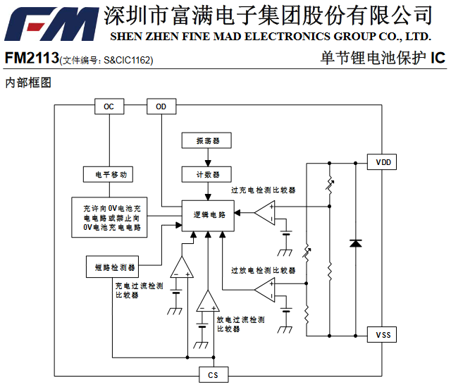
FM2113 Block Diagram
Its kind of fun (type-2 fun — quite frustrating in the moment) to find and implement these kind of parts from JLCPCB. It is actually more challenging to find appropriate parts given JLCPCB's attrocious search interface than it is to implement from a foreign language datasheet. I threw a couple key phrases into Google translate to confirm my assumptions, but for the most part I could make out what I needed to do from the block diagrams:
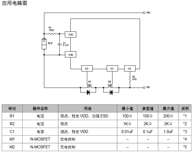
FM2113 Typical Application
USB-C
The previous version of this board used a surface mount micro USB connector, and I managed to rip one off of a board which required careful rework and epoxy to fix. Through hole USB-C connectors are much stronger and are the future, so I switched to that for this version. For an overview of how to upgrade a micro-USB design to USB-C, take a look at this Hackaday article. LINK
There are two sideband use pins on USB-C connectors which are often used these days to break out a second USB 2.0 pair for debug use. I hooked up the UART TX line (with BOM selectability of another GPIO pin) of the ESP32 to the SBU1 pin in case I ever wanted to interface this board with another of my project boards that doesn't support USB. One possible use case I was thinking about was having the ESP32 output discrete pulses for each radiation event over this sideband interface so that another board with a GPS could associate activity with location.
Software
Both this version of the board and this version of the board enumerate as USB vertual serial ports, but now that this board can operate without a USB cable connected, I added support in software for bluetooth. It's crappy copy pasta from examples, and it doesn't work with iPhones (they have neutered support for Bluetooth if you don't pay them) but it works reasonably well for Android. This lets you see real numbers on your phone instead of just listening to clicks.
This Arduino sketch can be found on Github here.
Radiation at Altitude
Dose from cosmic rays is a funtion of altitude. On the ground, many cosmic rays and secondary particles are shielded by the atmosphere. As altitue increases (to a point), flux increaes. Because most dose from cosmic rays is from secondary neutrons produced in a hadronic cascase in which a single sufficiently high energy cosmic ray will cause a shower of secondary neutrons, the altitude w absorbtion and generation of these secondaries are in equilibrium is the altitude of peak flux. Above this altitude, flux decreases untill you hit the lower Van Allen belt.

Background Radiation on a Commercial Flight
As a result, radition on a commercial flight will typically be 10-100x higher than radition on the ground. The plot here was recorded by one of my Geiger Couners on a flight between St. Louis, MO and Seattle, WA.